
التصميم لا يكفي ل CNC (التحكم العددي بالكمبيوتر) بالقطع, لكن التصميم على الجهاز (عبر تنسيق ملف CAD المناسب) يمكن أن تحدث فرقًا كبيرًا من حيث الدقة, الكفاءة, وحتى جدوى عملية التصنيع الخاصة بك. إذا كنت مصممًا, الميكانيكي, أو مهندس, ثم أنت على دراية بالمفهوم الذي يهم تنسيقات ملف CAD; تعتمد القدرة على الانتقال بسلاسة من الرقمية إلى الحقيقية على معرفة تنسيقات الملفات هذه.
سيؤدي هذا الدليل إلى تحطيم تنسيقات ملفات CAD الأكثر شيوعًا, بما في ذلك أفضل حالة استخدام لهم, وسوف يرشدك إلى أي تنسيق ملف لاستخدامه في مشروعك.
فهم تنسيق ملف CAD لآلات CNC
CAD (التصميم بمساعدة الكمبيوتر) الملفات هي التمثيل الرقمي للأجزاء أو التجميعات, حيث تم تصميم الأجزاء في برامج مثل SolidWorks, أوتوكاد, كاتيا, إلخ. يقومون بتخزين كل شيء من الهندسة الأساسية إلى أشد الميزات والتحملات.
يتم تحويل هذه الملفات عمومًا إلى CAM (بمساعدة الكمبيوتر التصنيع) لمساعدة الآلات على معرفة كيفية عملها وكيف يجب أن تصنع الأدوات. لكن, هذه العملية جيدة فقط مثل نوع التنسيق المستخدم. يجب اختيار تنسيق الملف الصحيح لتجنب فقدان البيانات وتفسير التصميم الدقيق.

كيفية اختيار أفضل تنسيق ملف لآلات CNC?
لا يوجد تنسيق ملف "أفضل" واحد لآلات CNC, ولكن هناك تنسيقات ملفات أكثر ملاءمة من غيرها. التنسيق المثالي:
- يحافظ على البيانات الهندسية وقصد التصميم
- إنه متوافق مع جهاز CNC أو برنامج CAM.
- يساعد في مشاركة البيانات بسهولة عبر منصات مختلفة
- يدعم النمذجة 2D و 3D
دعنا نستكشف المتنافسين.
مقارنة عملية التصنيع: التصنيع باستخدام الحاسب الآلي
فيما يلي جدول موجز لعمليات التصنيع المختلفة وتنسيقات الملفات الداعمة الخاصة بها:
| طريقة التصنيع | تنسيقات الملف الموصى بها | ملحقات الملف | حالة الاستخدام الأساسي |
| التصنيع باستخدام الحاسب الآلي | خطوة, إيجيس, الباراسوليد, محلي (تحول) | .STP/.step, .IGS/., .x_t/.x_b, .SLDPRT/.IPT/.CATPART | 3D جزء النمذجة & نقل الهندسة الدقيق |
| صب الحقن | خطوة, إيجيس, Solidworks, كاتيا | .STP/.step, .IGS/., .SLDPRT/.SLDASM, .CATPART/.CATPRODURCE | تصميم الأدوات & التجميعات المعقدة |
| تصنيع الصفائح المعدنية | دكسف, خطوة, DWG | . DXF, .STP/.step, .DWG | أنماط مسطحة, خطوط الانحناء, الملفات الشخصية |
| 3د الطباعة | المحكمة الخاصة بلبنان, خطوة, OBJ | .STL, .STP/.step, .OBJ | النماذج الأولية السريعة & التصنيع المضافة |
ما هي تنسيقات ملفات CAD الشائعة الأخرى المتاحة?
إلى جانب الخطوة ومعايير التبادل المحايد IGES, يميل المهندسون والمصممون إلى الاعتماد على مجموعة من تنسيقات ملفات CAD الأخرى لتناسب بعض تدفقات العمل. كل تنسيق له نقاط قوته, نقاط الضعف, وأفضل الاستخدامات, لذا فإن معرفة ما الذي يجب استخدامه يمكن أن يساعد في تدفق التصميم الخاص بك إلى التصنيع. نظرة عامة على هذه التنسيقات الشائعة, ما يقدمونه, وأين يفعلون أفضل ما يلي.
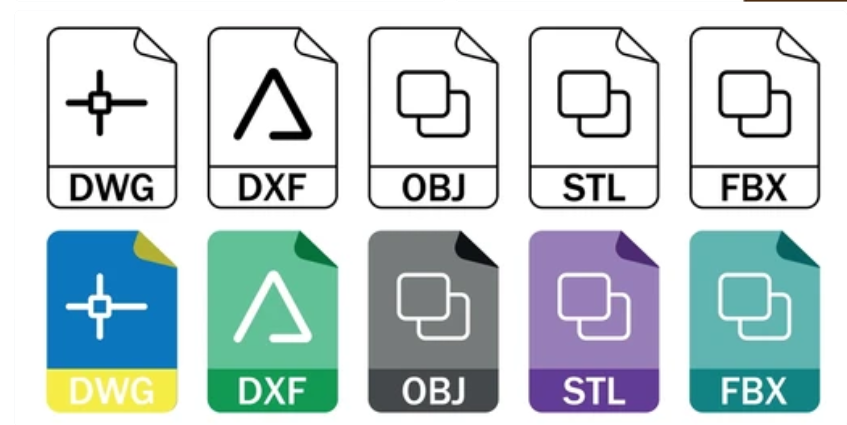
1. تنسيق ملف STL
أبسط وأكثرها استخدامًا هي STL (مجسم) الملفات. يتم تقريب شكل النموذج كشبكة للمثلثات, الذي يشفر فقط هندسة السطح للنموذج. لكن, ملفات STL صغيرة جدًا وسهلة المعالجة لأنها تفتقر إلى اللون, خصائص المواد, هياكل التجميع, وبيانات حدودي.
إنها نوبة طبيعية في بيئات التصنيع النماذج الأولية المنخفضة والمواد الإضافية حيث يكون الهدف هو الحصول على موهبة بصرية أو مادية بدلاً من قيادة أدوات قطع عالية الدقة.

2. تنسيقات ملف المتجه
الأشكال في تنسيقات المتجهات مثل SVG, منظمة العفو الدولية, ويتم وصف EPS رياضيا, ليس من حيث البكسل. لكن ما يشرقون في فعله هو تصوير هش, عمل فني ثنائي الأبعاد قابل للتطوير بلا حدود - مثل الشعارات, نص, والخطوط - للمدخلات وعلى الإطلاق مستويات التكبير وفقدان دقة الصفر.
لكن تنسيقات المتجهات لا تحتوي على أي معلومات ثلاثية الأبعاد حقيقية ، وبالتالي فهي غير مناسبة لعمليات طحن CNC أو تشغيلها. في تطبيقات CNC ثنائية الأبعاد مثل قطع الليزر, فينيل تخطيط, و Waterjet التنميط, سوف يتبع الجهاز مسارات الأدوات المستوية بناءً على منحنيات المتجهات, بدلا من بيانات البكسل.

3. تنسيق ملف DXF
Autodesk’s DXF (رسم تنسيق تبادل) تم تطويره لتعزيز التوافق بين أوتوكاد وأنظمة CAD الأخرى. إنه يخلق عملًا فعالًا لخط ثنائي الأبعاد, طبقة, التعليقات التوضيحية, والكيانات ثلاثية الأبعاد الأساسية, مما يجعلها مناسبة للصياغة والتصنيع. تملي ملفات DXF حركات الليزر, بلازما, وقواطع WaterJet مدفوعة بنمط دقيق وضبط تعريف خط الانحناء في متاجر الأغطية واللوحات.
بعض حزم CAM سوف تستورد بالفعل 3D DXF, لكن قوتهم تكمن في ملفات التعريف المستوية والرسومات التقنية بدلاً من النماذج الصلبة المفصلة.

4. تنسيق ملف DWG
التنسيق الخاص لـ AutoCad هو DWG, والتي تشمل المتجهات, بيانات التعريف, وخصائص الكائن وكذلك تخطيطات الألواح المدمجة. بسبب عالي المستوى من الإخلاص والدقة, إنه مثالي للغرامة, رسومات معمارية أو ميكانيكية مفصلة تتطلب أبعاد دقيقة ووثائق متعددة الأوراق.
الجانب السلبي هنا هو أن معظم الوقت, لا يمكن أن تقوم أنظمة CAM بتحليل ملفات DWG بالطريقة التي يمكن أن تتطلبها Autodesk-فهي تتطلب أدوات تحويل في عصر الفضاء أو المكونات الإضافية لاستخراج محتويات DWG بشكل صحيح. لكن, تظل DWG معيار الصناعة عند استخدام مخططات ثنائية الأبعاد أو مخططات تقنية معقدة يجب مشاركتها بين مستخدمي AutoCAD.

5. تنسيقات ملفات CAD أخرى خاصة
كل بائع CAD رئيسي, ما وراء المعيار المحايد, لديه تنسيق الملف الأصلي - SLDPRT في Solidworks, IPT في Autodesk Inventor, CATPART في كاتيا, وغيرها من الأسماء المماثلة في كريو, NX, وحافة صلبة. هذه التنسيقات الأصلية تلتقط كل ميزة, كل شجرة تاريخ, وكل معلمة في برنامج التصميم الأصلي, السماح بالتحرير السلس والربط الكامل.
لا تقبل منصات CNC و CAM عادةً ملفات الملكية مباشرة, من الشائع جدًا تصدير هذه النماذج إلى تنسيق محايد (خطوة أو Iges) قبل الآلات. تحافظ خطوة التحويل الإضافية هذه على نية التصميم مع ضمان التوافق في مجموعة واسعة من أدوات التصنيع.
AP203 مقابل. AP214 مقابل. AP242
اسمحوا لي أن أقدم موجزًا, جدول مفصل يوفر مقارنة جنبًا إلى جنب من AP203 مقابل. AP214 مقابل. AP242 من حيث التقنيات, استخدام الحالات, والاختلافات الواجهة.
| ميزة / يصف | AP203 | AP214 | AP242 |
| سنة الإصدار | 1994 | 2003 | 2014 |
| الاستخدام الأساسي | تبادل التصميم الميكانيكي | احتياجات صناعة السيارات والفضاء | التعريف القائم على النموذج (MBD), التصنيع الذكي |
| دعم الهندسة | هندسة صلبة | هندسة صلبة مع دعم التجميع | هندسة صلبة مع دعم التجميع المتقدم |
| بيانات المنتج | بيانات التصميم الأساسية | التحكم في التكوين, PDM | إدارة BOM, PMI, حركية |
| PMI (منتج MFG معلومات) | غير مدعوم | دعم محدود | الدعم الكامل, بما في ذلك GD&ت |
| هيكل التجميع | أساسي | تحسن | التجمعات الهرمية المتقدمة |
| توافق الإصدار | عفا عليها الزمن, الأنظمة القديمة | معتدل | الأكثر حداثة ومستقبل |
| دعم التصور | غير متوفر | محدود | يتضمن التصور النموذجي الفسيسي |
| الموصى بها ل | أجزاء بسيطة, أنظمة CAD/CAM الأقدم | السيارات, الفضاء الجوي, والتجمعات الكبيرة | صناعة 4.0, توأم رقمي, التصنيع عالي الدقة |
أفضل تنسيقات ملفات CAD لآلات CNC
يمكن لتنسيق ملف CAD الصحيح صنع أو كسر سير عمل CNC الخاص بك. التنسيقات الأربعة الأكثر موثوقية, من معظم دعم الصناعة والإخلاص, إلى الأسهل للاستخدام, مدرجة أدناه مع ما يجعلهم يتألقون على أرضية المتجر.
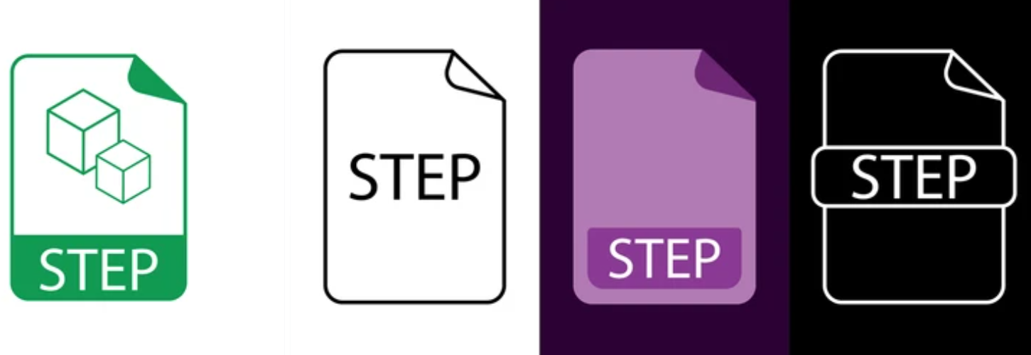
1. خطوة (.STP / .خطوة)
التنسيق ثلاثي الأبعاد المحايد للصناعة, خطوة, يحمل هندسة النموذج الصلبة الكامل ونية تصميم المستوى الأعلى (التجميعات, PMI, مواد). من الممكن موثوقية النقل هذه لأن كل نظام CAD و CAM رئيسي يدعمان الخطوة تقريبًا. يقدم AP214 أو AP242 ميزات التكوين وإدارة المنتج - DATA, و AP242 يدعم أيضًا التعريف القائم على النموذج (جي دي&T و PMI مضمنين في النموذج ثلاثي الأبعاد), إعطاء أفضل النتائج في تصنيع CNC.
2. إيجيس (.IGS / .Iges)
الخطوة تسبق IGES, ولكن سيكون مفيدًا لتبادل الهندسة البسيطة, خاصة في إعدادات الكاميرا القديمة أو المتخصصة للغاية. ستقوم الترجمات بإزالة ميزات حدودي, هيكل التجميع, والهيئات الخفية. إطارات الأسلاك, بقع السطح, ويمكن التعامل مع المواد الصلبة الأساسية, لكن قد تفقد هذا على الترجمة.
المشكلة هنا على ما يرام IGES للاستخدام عند العمل مع الآلات القديمة أو البرامج التي لا تقرأ الخطوة, ثم تحتاج إلى التحقق من أجسادك الصلبة قبل الالتزام بمسارات الأدوات.

3. الباراسوليد (.x_t / .x_b)
نواة النمذجة الهندسية تدعم العديد من أنظمة CAD المتقدمة (Siemens NX, حافة صلبة, Solidworks, إلخ.) هو الباراسوليد. الملفات المظلية هي ملفات kernel الأصلية, مما يؤدي إلى أعلى دقة في الميزات المعقدة, بما في ذلك العمليات المنطقية, شرائح, lofts, والرياضيات الدقيقة. Parasolid لا يهزم إذا كنت تقضي الكثير من وقتك في إحدى حزم CAD هذه واستخدمت أدوات CAM التي يتم قبول إدخال .x_t أو .x_b.
4. ملفات CAD الأصلية
إن تنسيق الجزء الذي يستخدمه كل بائع CAD الرئيسي هو الملكية (SLDPRT (Solidworks), IPT (Autodesk Inventor), CATPART (كاتيا), PRT (PTC أعتقد), وهكذا). هذه الملفات تعيش داخل أنظمةها الإيكولوجية, مع تاريخ الميزات الكاملة, الرسومات, والبيانات الوصفية, السماح بتعديل التصميم المستمر. للأسف, تحتاج معظم أنظمة CAM إلى واردات محايدة, لذلك عادةً ما تقوم بتصديرها إلى خطوة أو باراسوليد قبل التصنيع. لا تتجاهل أبدًا أسيادك الأصليين لأنك قد تحتاجهم لاحقًا للمراجعات المستقبلية.
كيفية تحويل ملفات CAD إلى تنسيق ملف CNC
تتضمن مراحل عملية تحويل نماذج CAD الخاصة بك إلى تنسيق جاهز لـ CNC تصدير أو ترجمة التصميم الخاص بك إلى ملف تبادل محايد (على سبيل المثال, خطوة, إيجيس, الباراسوليد) ثم استيراده إلى برنامج CAM يمنحك رمز الجهاز الفعلي (رمز G.). إليك نظرة عامة على خطوة بخطوة:
1. قم بإعداد نموذج CAD الأصلي الخاص بك
- إزالة الرسومات غير المستخدمة, إخفاء أو حذف هندسة البناء, قمع أي ميزة ليست ضرورية للتصنيع, وتنظيف الهندسة.
- تأكد من أن التصميم الخاص بك في ملليمتر أو بوصة; تحقق من أن طراز CAD الخاص بك يتطابق مع ما تريده للسيانين الفعلي الذي ستستخدمه.
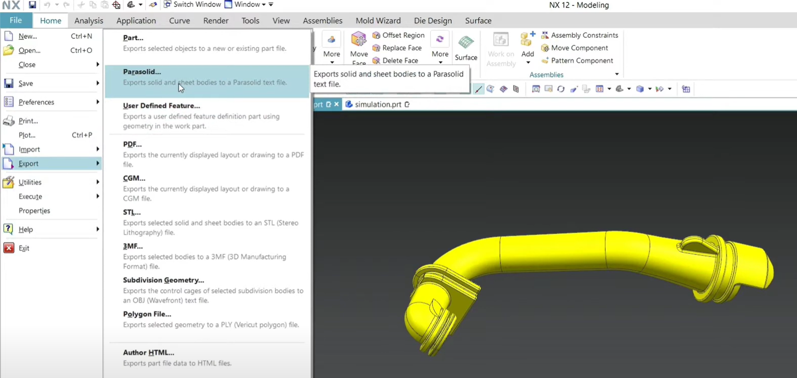
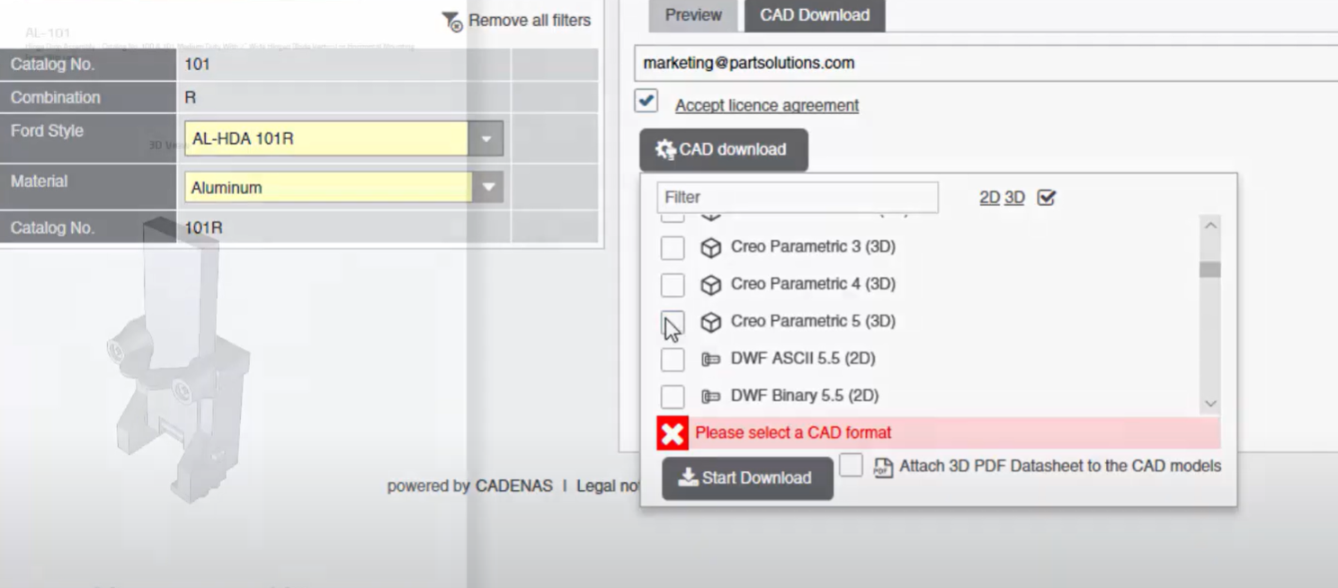
2. التصدير إلى تنسيق محايد
- انتقل إلى ملف → حفظ كما (أو تصدير) في تطبيق CAD الخاص بك و اختر حفظ على أنه تنسيق محايد, مثل الخطوة (.STP/.step), إيجيس (.IGS/.), أو الباراسوليد (.x_t/.x_b).

- تشديد إعدادات التسامح: على الرغم من أن معظم المصدرين يسمحون لك بتحديد التحملات الوهمية والزاوية, أكثر تشديد التسامح, أكبر حجم الملف. لأجزاء دقيقة, تهدف إلى توازن (على سبيل المثال, 0.01 ارتفاع الوتر).
- اذا كان ضروري, تشمل البيانات الأولية: الخطوة AP242 تدعم فقط تغيير الهندسة, لذلك لن يكون قادرًا على تصدير مؤشر مديري المشتريات (أبعاد, جي دي&ت) مطلوب لإبلاغ برنامج CAM الخاص بك عن ملاحظات التصنيع الحرجة. يجب تمكين تصدير PMI لإتاحته هذه البيانات.

3. التحقق من صحة الملف المصدر
- يمكن للمرء أن يفتح التصدير خطوة/ملف IGES في عارض محايد (Freecad, Edrawings, أو برنامج CAD نفسه), لكن, من الضروري تحقق من سلامة الهندسة: إذا كانت هناك وجوه مفقودة, القواعد الطبيعية المقلوبة, أو الأسطح غير المختلطة.
- إذا لم تنجح الأمور, قم بتغيير تحمل تصديرك أو قم بتغيير التنسيق (على سبيل المثال, من IGES إلى الخطوة).

4. استيراد إلى برنامج CAM
- لكن, من أجل البرنامج التعليمي, سنقوم بتحميل ملف CAD المحايد في حزمة CAM (الانصهار 360, Mastercam, كاميرا Solidworks, HSMWorks, إلخ.).
- أبعاد وتوجهات الأسهم إعادة تقييم الأسهم وتعويضات العمل (على سبيل المثال, G54) محددة.
- إذا لم تكتشف أداة CAM تلقائيًا, إعادة تطبيق أي معرفات (ثقوب, جيوب, فتحات).
5. قم بإنشاء مسار أدوات ومرحلة ما بعد العملية
- بناءً على الهندسة المستوردة, يمكنك إنشاء عمليات الطحن أو الدوران (الخشنة, التشطيب, حفر).
- تحقق من gouges, الاصطدام, أو مشكلات الوصول من خلال محاكاة مسارات الأدوات.
- يمكن لما بعد المعالج لبرنامج CAM تصدير رمز G الذي تم تنسيقه لوحدة التحكم في CNC المحددة الخاصة بك (فانوك, هاس, Heidenhain, إلخ.).
6. خياري: التحويلات الدُفزة أو الآلية
- إذا كنت تقوم بعمل كبير أو تكرار الوظائف, تصدير نصوص إلى ملف خطوة عبر API CAD (الماكرو Solidworks, نيكسو, أو بيثون سيناريو في فريبا,R T على سبيل المثال) يمكن أن يكون ممتعًا للسيناريو وأتمتة الخطوة أو الجيل المظلي.
- بعض أدوات الطيران الثالث (على سبيل المثال, مبادل CAD, Datakit) تقديم قدرات ترجمة الدُفعات عبر عشرات التنسيقات.
تنسيقات مدعومة إضافية في برنامج CNC الحديث
إلى جانب التنسيقات المذكورة أعلاه, هناك بعض التنسيقات الأخرى التي تساعدنا في برنامج CNC الحديث.
- XT-BREP مع JT: ملفات خفيفة الوزن مناسبة للعرض والمشاركة.
- ملفات Autodesk Inventor (.IPT, .هدف): مدعومة بالكامل من أدوات CAM التابعة لـ Autodesk.
- أنظمة ملفات Dassault Ecosystem Catia V5: عظيم للفضاء, خصوصاً.
- مع جناح PTC, أفضل استخدام مع creo parametricالملفات: قدرات النمذجة القوية.
- تطبيقات CNC: قوي للغاية, غالبًا ما تستخدم في Siemens NX و Solidworks
أهمية الرسومات الفنية ثنائية الأبعاد في تصنيع CNC
هذا هو الوضع: حتى لو كان لديك نموذج ثلاثي الأبعاد مثالي:
- تحديد التسامح والمواضيع
- البعد الهندسي والتسامح (جي دي&ت)
- صنع ميزات مثل Chamfers, عمق, وإنهاء أكثر وضوحا
- ملاحظات للتجميع, تقتيش, أو ما بعد المعالجة

خاتمة
عند اختيار تنسيق ملف CAD الصحيح لآلات CNC, إنه أكثر من مجرد قرار فني - إنه وسيلة لضمان ظهور تصاميمك بالطريقة التي تنويها. هناك تنسيقات مثل الخطوة و Iges التي تستخدم على نطاق واسع بسبب عالميها وتوافقها;ذ, لكن, من خلال تجاوز إيجابيات وسلبيات كلا التنسيقين, سيكون لديك ميزة كبيرة في التصنيع.
إذا كنت تقوم بتصدير شريحة بسيطة أو مكون مركب فضاء, يعتمد النجاح على قدرتك على مطابقة تنسيق ملف CAD مع متطلبات CNC لضمان الدقة, كفاءة, والنجاح.
الأسئلة الشائعة
- كيف يمكنني حفظ أو تخزين هذا الملف لآلات CNC?
خطوة (.STP أو .step) التنسيق هو الأكثر استخدامًا ويمكن الاعتماد عليه لآلات CNC.
- هل هناك ملفات STL جاهزة متاحة للآلات CNC?
نعم, من الناحية الفنية, لكن ملفات STL لم يكن لها أي دقة لهم - كانت أفضل بكثير للطباعة ثلاثية الأبعاد. يتم استبعاد بيانات Parametric والتصنيع.
- كيف تختلف ملفات الخطوة و IGES عن بعضها البعض?
يمكن تخزين المزيد من البيانات الوصفية في ملفات الخطوة لكل من النمذجة السطحية والصلبة. إنه أقدم ويتكون في الغالب من الأسطح والأوفار السلكي ل IGES.
- هل هو جيد لآلات CNC إذا كان ملف CAD أصلي?
لأغراض الآلات, يميلون إلى التحول إلى تنسيقات محايدة مثل الخطوة أو Iges, ولكن مثالية للاستخدام الداخلي.
- هل من الممكن تحويل ملف CAD إلى مثل هذا التنسيق لاستخدام CNC?
قم بتصدير الملف إلى نوع الملف للخطوة, إيجيس, أو parasolid باستخدام وظيفة التصدير الخاصة ببرنامج CAD الخاص بك. تحقق من التوافق مع برنامج CAM الخاص بك.
- هل ما زلت مطلوبًا لإنشاء رسومات ثنائية الأبعاد إذا كنت أمتلك بالفعل نموذجًا ثلاثي الأبعاد?
نعم, 2تتضمن الرسومات D تفاصيل مثل التسامح, الخيوط, وملاحظات الآلات التي قد لا تكون واضحة تمامًا في نموذج ثلاثي الأبعاد.
7. كيف تقوم الآلات CNC بتكييف ملفات CAD للمنتجات المعمارية?
أ: يتم تحويل الأشكال الهندسية المعقدة لملفات CAD إلى مسارات الأدوات, في التصنيع باستخدام الحاسب الآلي, لتوفير أنماط ثقب دقيقة ومحاذاة متناظرة, الذي ينتج الجودة, متين, الكسوة المعدنية المثقبة تلبية الاحتياجات المعمارية والمتطلبات الجمالية.
![]()


1 فكرت في "فهم تنسيق ملف CAD لآلات CNC”