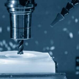
الرسومات الفنية هي جزء مهم من عملية التصنيع. سواء كنت تنتج أجزاء من CNC الآلي, مكونات الصفائح المعدنية, المنتجات المقدمة الحقن, أو قطع الغيار -يضمن رسم فني جيد الإعداد جيدًا تصنيع تصميمك بدقة.
في هذا الدليل, سنغطي كل ما يحتاج المهندسون إلى معرفته حول إعداد الرسومات التقنية المهنية للتصنيع, بما في ذلك معايير الرسم, العناصر الرئيسية, نصائح برمجيات CAD, ومتطلبات رسم محددة لعمليات التصنيع المختلفة.
لماذا الرسومات الفنية مهمة للغاية في التصنيع?
فكر في رسم فني مثل دليل التعليمات التفصيلي لصنع منتجك. يخبر المصنع:
كيف يبدو الجزء من كل زاوية
الحجم الدقيق لكل ميزة
ما هي المواد التي يجب استخدامها
كيف يجب أن يكون السطح ناعمًا أو خشنًا
كيف ضيقة أو فضفاضة أجزاء معينة تحتاج إلى أن تتناسب معا
بدون هذه التفاصيل, يجب أن يخمن المصنع - ويمكن أن يؤدي التخمين إلى أخطاء, تأخير, أو تكاليف إضافية.
تساعد الرسومات الفنية على تجنب الأخطاء المكلفة
التصنيع هو كل شيء عن الدقة. حتى خطأ صغير في الحجم أو الشكل يمكن أن يسبب مشاكل كبيرة - خاصة بالنسبة للأجزاء المستخدمة في الآلات, سيارات, أو الالكترونيات. الرسومات الفنية تأكد من أن الجميع - من المهندس إلى مشغل الماكينة - على نفس الصفحة.
الرسومات الفنية هي لغة عالمية
سبب آخر يهم الرسومات هو أنها تستخدم الرموز والقواعد القياسية التي يفهمها الأشخاص في جميع أنحاء العالم. ما إذا كانت أجزائك تصنع في الصين, ألمانيا, أو الولايات المتحدة الأمريكية, يساعد الرسم الفني المناسب في تجنب سوء الفهم.
تساعد الرسومات الفنية على التحكم في جودة
أخيراً, تحدد الرسومات الفنية معايير الجودة لمنتجك. يخبرون الشركة المصنعة بالضبط ما تتوقعه - ويعطونك شيئًا للتحقق منه عند وصول الأجزاء النهائية.
باختصار, إذا كنت تريد أن يكون منتجك صحيحًا في المرة الأولى - في الوقت المحدد وعلى الميزانية - لا تتخطى الرسم الفني أبدًا!
المعايير الدولية للرسومات التقنية
تشبه معايير الرسم الفني "قواعد اللعبة". يتأكدون من أنه بغض النظر عن مكان صنع أجزائك - في الصين, أوروبا, أو أمريكا - الجميع يفهم نفس الرموز, القياسات, والإرشادات.
بدون هذه المعايير, قد ترسم كل شركة الأمور بشكل مختلف, مما يؤدي إلى الارتباك, أخطاء, أو التأخير في الإنتاج.
المعايير الأكثر شيوعا التي يجب أن تعرفها
هناك نظامان رئيسيان يستخدمان في جميع أنحاء العالم للرسومات الفنية:
معايير ISO (المنظمة الدولية للتوحيد)
تستخدم أساسا في أوروبا, آسيا, وأجزاء أخرى كثيرة من العالم.
يركز على الوحدات المترية (ملليمتر, سنتيمتر).
يتضمن إرشادات لأنواع الخطوط, الرموز, الأبعاد, التسامح, و اكثر.
المعايير المشتركة:
ايزو 2768 (التسامح العام)
ايزو 1302 (نسيج السطح)
معايير ASME (الجمعية الأمريكية للمهندسين الميكانيكيين)
تستخدم في الغالب في الولايات المتحدة.
يركز على الوحدات الإمبراطورية (بوصة) ولكن أيضا يدعم المقياس.
المعيار المعروف: ASME Y14.5-هذا هو دليل الانتقال للبعيد والتحمل (جي دي&ت), مما يساعد على التحكم في الشكل, مقاس, وموقف الميزات من جزء.
لماذا المعايير مهمة جدا?
تخيل إرسال الرسم الخاص بك إلى مصنع في الخارج - إذا كنت لا تستخدم تنسيقًا قياسيًا, قد لا يفهم المهندسون رموزك أو تعليماتك. هذا يمكن أن يؤدي إلى:
أحجام الأجزاء الخاطئة
سوء السطح ينتهي
مواضع ثقب غير صحيحة
فحوصات الجودة الفاشلة
ولكن عندما تتبع معايير ISO أو ASME, الجميع يتحدث نفس "لغة الرسم التقنية". يجعل عملية التصنيع أسرع, أسهل, وأكثر دقة.
نصيحة للمهندسين والمصممين
تحقق دائمًا من المعيار الذي تفضله الشركة المصنعة قبل إرسال رسوماتك. على سبيل المثال:
| منطقة | المعيار المشترك المستخدم |
| أوروبا/آسيا | معيار ISO |
| الولايات المتحدة الأمريكية/كندا | معيار ASME |
باتباع المعايير المناسبة العروض الاحترافية - وهو يوفر الوقت والمال لك وللصنع الخاص بك.
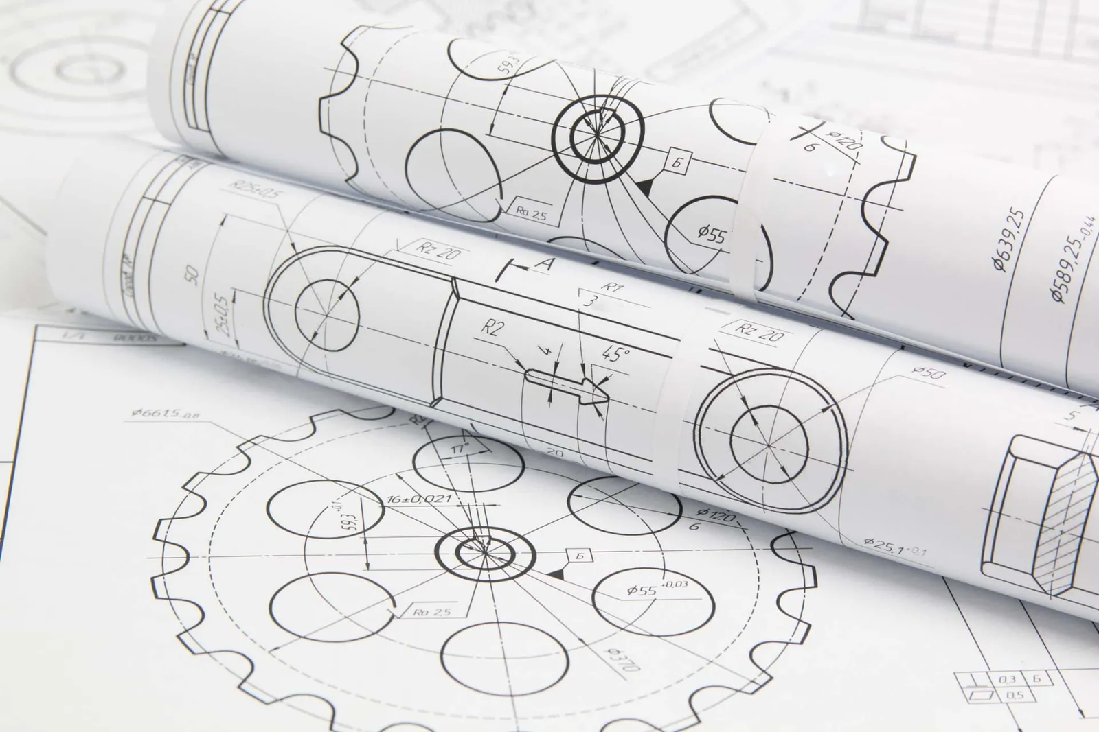
العناصر الرئيسية للرسم الفني
الرسم الفني أكثر من مجرد رسم - إنه يشبه دليل التعليمات التفصيلي لإنشاء جزء منه. كل سطر, ملحوظة, والرمز له غرض. إذا كان هناك شيء مفقود أو غير واضح, يمكن أن يؤدي إلى أخطاء الإنتاج أو التأخير.
دعنا نتفكك أهم الأجزاء التي يجب أن يكون لدى كل رسم تقني جيد.
كتلة العنوان
عادة ما يوجد في الركن الأيمن السفلي من الرسم. يوفر معلومات أساسية مثل:
اسم الجزء
رقم الجزء
مادة
حجم (ما مدى حجم الرسم أو صغيرته بالجزء الحقيقي)
تاريخ الرسم
اسم المصمم أو المهندس
تاريخ المراجعة (يظهر ما إذا كان قد تم تحديث الرسم)
فكر في كتلة العنوان مثل بطاقة هوية الرسم - فهي تساعد الناس على معرفة ما يبحثون عنه.
وجهات نظر الجزء (2د أو 3D)
تُظهر معظم الرسومات مناظر مختلفة لجزء لإعطاء صورة كاملة. وتشمل المناظر المشتركة:
عرض الجبهة
منظر أعلى
عرض جانبي
عرض القسم (يظهر قطع داخلي)
عرض متساوي القياس أو ثلاثي الأبعاد (اختياري ولكن مفيد)
تساعد وجهات نظر متعددة المصنع على فهم الشكل, مقاس, وتفاصيل الجزء الخاص بك من كل زاوية.
أبعاد
هذا هو واحد من أهم أجزاء أي رسم فني. تخبر الأبعاد المصنع بالضبط حجم كل شيء.
الأبعاد النموذجية تشمل:
طول, عرض, ارتفاع
حجم الثقب والموقع
سمك الجدران
دائرة نصف قطرها أو قطر المنحنيات
استخدم دائمًا أبعاد واضحة ودقيقة. إذا كان على المصنع أن يخمن - فهذه أخبار سيئة.
التسامح
تخبر التسامح بالمصنع مقدار التباين المسموح به في حجم الجزء الخاص بك.
على سبيل المثال:
حجم ثقب 10 مم ± 0.1 مم يعني أن الثقب يمكن أن يتراوح بين 9.9 مم و 10.1 مم ولا يزال على ما يرام.
التسامح مهمة لأنه لا توجد عملية تصنيع مثالية - الأجزاء لها دائمًا اختلافات صغيرة. لكن كلما كان التسامح أكثر إحكاما, كلما زادت التكلفة.
رموز الانتهاء من السطح
توضح هذه الرموز مدى سلاسة أو خشنة السطح.
على سبيل المثال:
سيكون للجزء الذي يحتاج إلى تلميع أو تصنيع رمز إنهاء السطح مع قيمة خشونة محددة (مثل RA 3.2μm).
بدون هذه الرموز, لا يعرف المصنع ما إذا كان يجب أن يكون السطح خشنًا, سلس, أو لامعة.
ملاحظات وتعليمات خاصة
أحيانا, ستحتاج إلى إضافة ملاحظات إضافية للأشياء التي لا تتناسب مع الفئات الأخرى. هذا يمكن أن يشمل:
متطلبات المواد
تعليمات المعالجة الحرارية
طلاء السطح (مثل الأنود أو الرسم)
تعليمات التجميع
متطلبات فحص الجودة
يجب أن يجيب رسم جيد على كل سؤال قبل طرحه.
لا تخمين. لا افتراضات. لا أخطاء.
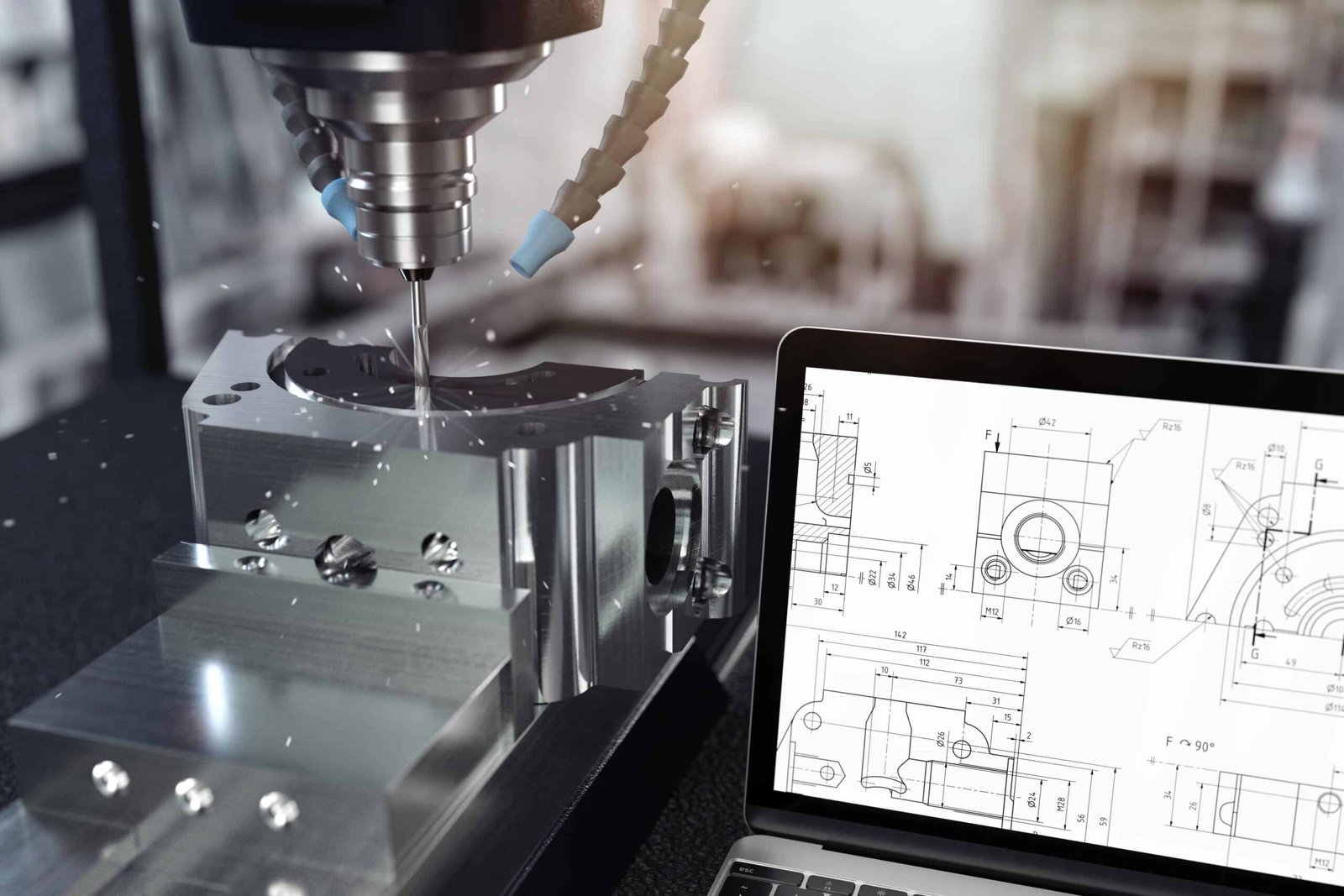
إعداد رسم فني مع برنامج CAD
إذا كنت جديدًا على CAD, قد تتساءل - كيف أقوم برسم تقني جيد في الواقع?
إليك دليل بسيط خطوة بخطوة لمساعدتك في البدء.
خطوة 1: ابدأ بنموذج ثلاثي الأبعاد
قبل أن تبدأ الرسم ثنائي الأبعاد الخاص بك, يقوم معظم المهندسين بإنشاء نموذج ثلاثي الأبعاد للجزء في برنامج CAD الخاص بهم (مثل Solidworks, أوتوكاد, أو الانصهار 360).
هذا النموذج ثلاثي الأبعاد يمنحك:
الشكل الصحيح للجزء
الأبعاد الدقيقة
فكرة واضحة عن كيفية ظهورها وتناسبها
بمجرد أن يبدو الطراز ثلاثي الأبعاد جيدًا, يمكنك إنشاء رسومات تقنية ثنائية الأبعاد مباشرة منها. هذا يوفر طنًا من الوقت مقارنة بالرسوم من الصفر.
خطوة 2: أضف طرق عرض مختلفة
بعد إنشاء نموذج ثلاثي الأبعاد الخاص بك, الخطوة التالية هي إدراج طرق عرض ثنائية الأبعاد في ورقة الرسم الخاصة بك.
وتشمل المناظر المشتركة:
عرض الجبهة
منظر أعلى
عرض جانبي
عرض القسم (إذا لزم الأمر لإظهار التفاصيل الداخلية)
3D أو عرض متساوي القياس (خياري, لكن مفيدة)
اختر المشاهد التي تُظهر أفضل الميزات المهمة من الجزء الخاص بك.
خطوة 3: إضافة الأبعاد
بمجرد أن تكون وجهات نظركم في مكانها, لقد حان الوقت لإضافة أبعاد. تكون واضحة ومفصلة قدر الإمكان.
تذكر أن تشمل:
الحجم الكلي (طول, عرض, ارتفاع)
مواقف وأحجام الثقب
سمك الجدار
نصف القطر والزوايا
القياسات الحرجة التي تؤثر على الوظيفة
نصيحة محترف: لا تضيف الكثير من الأبعاد غير الضرورية - فقط ما هو مطلوب للإنتاج.
خطوة 4: وضع التسامح
بعد إضافة الأبعاد, يجب عليك تحديد التسامح-خاصة بالنسبة للميزات المهمة أو عالية الدقة.
هناك طريقتان لوضع التسامح:
أضف تسامحًا محددًا بجوار البعد
أو, حدد التسامح العام في كتلة العنوان (على سبيل المثال: ± 0.1mm ما لم ينص على خلاف ذلك)
كن ذكيًا هنا - إن التحمل الضيق يعني ارتفاع التكاليف!
خطوة 5: أضف متطلبات المواد والسطح
التالي, أخبر المصنع ما المادة التي يجب أن يكون الجزء, وكيف يجب أن يبدو السطح أو يشعر.
أمثلة:
مادة: الألومنيوم 6061, الفولاذ المقاوم للصدأ 304, ABS البلاستيك
صقل الأسطح: السطح المعني RA 3.2 ميكرومتر
طلاء: بأكسيد, رسمت, مصقول, إلخ.
يمكن أن تدخل هذه المعلومات إلى كتلة العنوان أو كملاحظة منفصلة.
خطوة 6: أضف ملاحظات وتعليمات خاصة
في بعض الأحيان ، هناك تفاصيل لا تتناسب مع الرسم الرئيسي - مثل:
المعالجة الحرارية
تعليمات التجميع
تفاصيل المعالجة السطحية
معايير فحص الجودة
متطلبات التغليف
أضف هذه الملاحظات الواضحة على الرسم.
خطوة 7: تحقق من كل شيء بعناية
قبل إرسال الرسم إلى المصنع, تحقق من كل شيء:
هي كل الآراء المهمة المدرجة?
هل الأبعاد صحيحة?
هل التسامح معقول?
هل المواد المحددة?
هل كل الإرشادات الخاصة واضحة?
الأخطاء في الرسم = التأخير, تكاليف أعلى, أو أجزاء سيئة.
من السهل فهم أفضل الرسومات الفنية - حتى بالنسبة للأشخاص الذين لا يتحدثون لغتك جيدًا.
تجنب التفاصيل غير الضرورية. استخدم الرموز القياسية. وفكر دائمًا من وجهة نظر المصنع.
رسم واضح يوفر الوقت, مال, والتوتر للجميع.
متطلبات محددة لعمليات التصنيع المختلفة
تحتاج طرق التصنيع المختلفة إلى أنواع مختلفة من المعلومات على الرسم الفني الخاص بك.
دعنا نقسمه بطريقة بسيطة.
رسومات تصنيع CNC - ما يجب تضمينه
يستخدم Machining CNC أدوات القطع لإزالة المواد من كتلة من المعدن أو البلاستيك.
ما هي المصانع التي تريد رؤيتها في الرسم الخاص بك:
الأبعاد الدقيقة لكل ميزة
التسامح مع الثقوب, فتحات, تسطيح, إلخ.
الانتهاء من السطح (على سبيل المثال, را 3.2 ميكرومتر)
المواضيع والثقوب المستغلة (مع شرح قياسي)
نوع المواد
أي متطلبات تصنيع خاصة (مثل الحواف الحادة, تشامفيرز, أو deburring)
نصيحة محترف: أضف فقط التحمل الضيق حيث يهم حقًا. يمكن أن تصبح باهظة الثمن!
الرسومات المعدنية ورقة - ما يجب تضمينه
تصنع الأجزاء المعدنية ورقة عن طريق الانحناء, قطع, واللكم صفائح معدنية مسطحة.
ماذا تظهر على الرسم الخاص بك:
عرض النمط المسطح (قبل الانحناء)
خطوط واتجاهات ثني
انحناء دائرة نصف قطرها وزوايا
أحجام ومواقف الثقب
سمك المواد
المعالجة السطحية (مثل طلاء المسحوق أو الأنود)
نصيحة محترف: تذكر أن الثني المعدني يمتد قليلاً أو يضغط على المادة - لذا أضف ملاحظة حول بدلات الانحناء إذا لزم الأمر.
رسومات صب الحقن - ما يجب تضمينه
صب الحقن مخصص للأجزاء البلاستيكية المصنوعة عن طريق حقن البلاستيك المنصهر في قالب.
أشياء مهمة لإظهارها:
زوايا مسودة (عادة 1 ° - 3 °) للمساعدة في إطلاق الجزء من القالب
سمك الجدار (سمك موحد هو الأفضل)
الأضلاع وهياكل الدعم للقوة
مواقع دبوس البوابة والقاذف (إذا لزم الأمر)
نوع المواد (عضلات المعدة, الكمبيوتر, نايلون, إلخ.)
الانتهاء من السطح (لامع, مادة, محكم)
نصيحة محترف: إذا لم تكن متأكدًا من تصميم زوايا أو تصميم العفن, اطلب من المصنع النصيحة - يفعلون ذلك كل يوم.
يموت الرسومات الصب - ما يجب تضمينه
يتم استخدام صب القالب لصنع الأجزاء المعدنية (مثل الألومنيوم أو الزنك) مع الأشكال المعقدة.
التفاصيل الرئيسية لإضافة:
زوايا مسودة (على غرار صب الحقن)
سمك الجدار (تجنب سميكًا جدًا أو رقيقًا جدًا)
شرائح أو نصف قطرها لتجنب الزوايا الحادة
نوع المواد (الألومنيوم ADC12, سبائك الزنك, إلخ.)
الانتهاء من السطح (كما, أطلق النار, رسمت)
أي مناطق تصنيع بعد الصب
نصيحة محترف: غالبًا ما تحتاج أجزاء الصب التي تموت في غالب.
كل عملية تصنيع لها قواعدها الخاصة.
قبل إرسال الرسم الخاص بك, اسأل نفسك:
"إذا كنت أقوم بهذا الجزء مع هذه العملية, ماذا أحتاج إلى معرفته?"
واضح, تساعد الرسومات البسيطة على المصنع لجعل أجزائك أسرع, أرخص, ومع وجود أخطاء أقل.
النصائح النهائية للمهندسين
الرسومات الفنية هي أساس التصنيع الناجح. يضمن الرسم المعروف جيدًا أن يتم إنتاج أجزائك بشكل صحيح, بسرعة, وداخل الميزانية.
باتباع المعايير الدولية, باستخدام تقنيات CAD المناسبة, وتخصيص الرسومات لعمليات التصنيع المحددة, يمكن للمهندسين تجنب الأخطاء المكلفة وتقديم منتجات عالية الجودة.
الربط الداخلي:
صب الحقن مقابل الآلات CNC: ماهو الفرق?
![]()