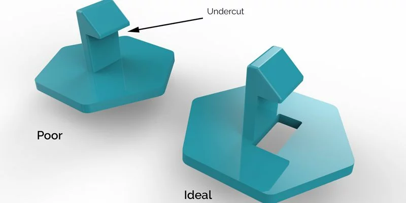
تعتبر التخفيضات أحد أكثر الجوانب تحديًا صب حقن البلاستيك تصميم. إنها الميزات التي تمنع إخراج الجزء المصبوب في قالب سحب مستقيم بسيط - عادةً لأن الشكل الهندسي يقفل الجزء داخل الأداة.
في صب الحقن, و تقويض يمكن أن تتخذ أشكالا عديدة: ثقب جانبي, أخدود, عطلة, أو هوك جاحظ. غالبًا ما تضيف هذه الميزات وظائف أساسية، مثل التثبيت, ختم, أو المحاذاة، ولكنها أيضًا تجعل بناء القالب أكثر تعقيدًا.
وتشمل الأمثلة الشائعة:
ال الخيوط على قفل من البلاستيك.
أ فتحة لزر الطاقة الموجود على علبة الجهاز.
قفل علامات التبويب على عدسة الضوء الخلفي.
زعماء الزاوية أو الأخاديد في العلب الميكانيكية.
في حين أن التخفيضات غالبا ما تكون لا مفر منها, ويمكن إدارتها من خلال الهندسة الذكية. توضح الطرق الستة التالية كيفية تصميم الأجزاء وتشكيلها باستخدام الأجزاء السفلية بكفاءة - دون التضحية بالجودة أو زيادة التكاليف.
1. ضبط خط الفراق
تحويل القالب خط فراق غالبًا ما تكون أسهل طريقة لاستيعاب الأجزاء السفلية.
عن طريق تعديل اتجاه القالب أو هندسة الفراق, يمكنك وضع الجزء السفلي بحيث يتماشى مع خط الفراق. وهذا يسمح بتكوينه بواسطة نصفي القالب وإطلاقه بشكل نظيف عند الطرد.
مثال:
إذا كان الجزء الخاص بك يتضمن مواجهات جانبية أو زعماء صغار, قد يؤدي تحريك خط الفراق وضبط زوايا المسودة إلى إلغاء الحاجة إلى آليات إضافية.
مزايا:
يبسط الأدوات والصيانة.
يقلل التكلفة مقارنة بالإجراءات الجانبية.
تمكن دورات صب أقصر.
اعتبارات:
قد يؤثر على الأسطح التجميلية أو اتجاه الجزء.
يتطلب تقييمًا دقيقًا لتدفق المواد ومسارات التبريد.
عندما تمنع هندسة الجزء أو الاتجاه هذه الطريقة, الإجراءات الجانبية هي الاختيار المنطقي التالي.
2. استخدام الإجراءات الجانبية (شرائح كام)
الإجراءات الجانبية- ويسمى أيضا شرائح الكاميرا- هي عناصر قالب ميكانيكية تتحرك بشكل عمودي على اتجاه فتح القالب لتكوين ميزات تقويضية.
كيف يعملون:
عندما يغلق القالب, يقوم دبوس الكامة بتحريك الحركة الجانبية إلى موضعها.
بعد الحقن والتبريد, يفتح القالب, ويتراجع العمل الجانبي لمسح التقويض.
التطبيقات النموذجية:
خرطوم لاذع ومكونات أنبوبي.
مقابض, مقابض التحكم, والموصلات.
الأجزاء ذات الفتحات أو التجاويف المتعامدة مع خط الفراق.
المواصفات الفنية:
أقصى عرض: 8.419 في (213.84 مم)
أقصى ارتفاع: 2.377 في (60.38 مم)
ماكس السفر: 2.900 في (73.66 مم)
أفضل المواد:
الراتنجات الصلبة مثل نايلون (السلطة الفلسطينية), البولي (الكمبيوتر), و أسيتال (بوم) مثالية. مواد مرنة مثل البولي إثيلين المنخفض الكثافة أو TPE قد تلتصق أثناء التراجع, لذا فكر في الصدمات بدلاً من ذلك.
الايجابيات:
تمكين الميزات المفصلة والوظيفية للغاية.
يحافظ على التكرار العالي.
مناسبة للأتمتة, إنتاج كبير الحجم.
سلبيات:
يزيد من تعقيد الأدوات والتكلفة.
يتطلب مساحة لحركة الكاميرا داخل قاعدة القالب.
على الرغم من الاستثمار الإضافي, تعد الإجراءات الجانبية إحدى الطرق الأكثر موثوقية لتشكيل ميزات تقويض دقيقة.
3. نتوءات (تجريد Undercuts)
نتوءات تعتمد على مرونة البلاستيك المصبوب بدلاً من الحركة الميكانيكية. هذه الطريقة مثالية ل تصميمات ملائمة, أغطية الحاويات, وأغطية مرنة.
كيف يعملون:
سلس, إدراج radiused يشكل تقويض. أثناء القذف, الجزء ينثني على الميزة, مما يسمح لها بـ "التخلص من" قلب القالب دون تمزيق.
مواد مناسبة:
البولي إثيلين المنخفض الكثافة (بولي إيثيلين قليل الكثافة)
TPE (المطاط الصناعي بالحرارة)
تي بي يو (البولي يوريثان بالحرارة)
نصائح التصميم:
حافظ على التحولات تدريجية، وتجنب الحواف الحادة.
الحد من عمق القطع لتسهيل التحرير.
استخدم لوحة القاذف لضغط القذف الموحد.
مزايا:
يزيل الأجزاء المتحركة, تقليل الصيانة.
يقصر دورات صب.
ممتاز للمكونات المرنة الصغيرة.
ملاحظة على صب LSR:
مطاط السيليكون السائل (LSR) يتيح القالب - نظرًا لمرونته - إجراء عمليات قطع أكثر عدوانية وهندسة معقدة, مما يجعلها الخيار الأفضل للأختام, الحشيات, والموصلات المرنة.
4. إدراجات محملة باليد
عند التعامل مع الأشكال الهندسية المعقدة أو عمليات الإنتاج الصغيرة, إدراجات محملة باليد هي خيار عملي.
ما هم:
هذه عبارة عن إدخالات معدنية يتم وضعها يدويًا في القالب قبل كل دورة حقن لمنع تجاويف أو ميزات معينة. بعد صب, تتم إزالة الملحق وإعادة استخدامه.
التطبيقات:
مساكن الأجهزة الطبية, حاويات إلكترونية, أو أي جزء لا تكون فيه الشرائح الآلية فعالة من حيث التكلفة.
مزايا:
تكلفة الأدوات منخفضة.
مثالية للنماذج الأولية وعمليات التشغيل المحدودة.
يتجنب إجراءات العفن المعقدة.
محددات:
أوقات دورة أبطأ بسبب المناولة اليدوية.
يتطلب قفازات مقاومة للحرارة من أجل سلامة المشغل.
يجب أن يكون حجم الإدخال مريحًا - ويفضل ذلك 0.5 في² أو أكبر, ولكنها أصغر من مجموعة أوراق اللعب.
يُستخدم هذا النهج على نطاق واسع للتحقق من صحة التصميم ومراحل الإنتاج المبكرة حيث تكون مرونة القالب أمرًا أساسيًا.
5. تصغير (انزلاق) عمليات الإغلاق
تصغير الإغلاق, وتسمى أيضا إغلاق انزلاق, السماح لأجزاء القالب بالانزلاق إلى بعضها البعض, تشكيل ميزات القفل الذاتي دون مكونات متحركة منفصلة.
كيف يعملون:
يتضمن نصف القالب إسقاطًا آليًا يعمل على "التلسكوبات" في تجويف مماثل على الجانب الآخر, إيقاف تدفق المواد بشكل فعال وتشكيل المنطقة السفلية.
التطبيقات:
مقاطع المفاجئة أو آليات الإغلاق.
وصلات على شكل خطاف.
مكونات العلبة المتشابكة.
فوائد:
يبسط تصميم الأدوات.
يقلل من الصيانة والتآكل.
يلغي الحاجة إلى إجراءات جانبية أو إدراجات.
إرشادات التصميم:
يمد ما لا يقل عن 3 درجات من المسودة لكل جانب لمنع تآكل المعدن على المعدن, وامض, أو تلف العفن المبكر.
6. تحسين تصميم الأجزاء والعمليات الثانوية
حتى أفضل تصميم للقالب لا يمكنه التعويض عن هندسة الأجزاء الضعيفة. تصميم قابل للتصنيع (سوق دبي المالي) يبقى حاسما لقولبة موثوقة.
المبادئ التوجيهية الرئيسية:
يضيف زوايا مسودة (الحد الأدنى 1-3 درجة) لسهولة الطرد.
يحافظ على سمك الجدار موحد لتجنب تزييفها.
يستخدم الأضلاع ونصف القطر لتقوية الأسطح المسطحة.
قم بإزالة الأجزاء السميكة لمنع علامات الحوض.
يتقدم تشطيب السطح الدقيق فقط عند الاقتضاء.
نصيحة لتحسين التكلفة:
للنماذج الأولية أو الأجزاء ذات الحجم المنخفض, غالبًا ما يكون من الاقتصادي أكثر تشكيل شكل بسيط وميزات معقدة للآلة بعد الاستخدام العمليات الثانوية مثل الحفر أو الطحن.
الاستفادة من أدوات سوق دبي المالي:
قم بتحميل نموذج CAD الخاص بك إلى النظام الأساسي الخاص بالشركة المصنعة لديك لإجراء تحليل سوق دبي المالي الآلي الذي يضع علامات على التخفيضات, مشاريع القضايا, وعدم تناسق سمك الجدار قبل بدء الإنتاج.
التوصيات النهائية
تعتبر الأجزاء السفلية جزءًا طبيعيًا من تصميم الأجزاء المعقدة، ولكن باستخدام الاستراتيجيات الصحيحة, ليس عليهم تعقيد مشروعك.
قبل الانتهاء من تصميم القالب الخاص بك:
قم بتقييم جميع القطع السفلية مبكرًا لتقليل تغييرات الأدوات.
ضع في اعتبارك حجم الإنتاج ومقايضات التكلفة طويلة المدى.
ناقش خياراتك مع خبراء تصميم القوالب لتحديد الحل الأكثر كفاءة.
لا تتجاهل طرق ما بعد المعالجة لعمليات إنتاج أبسط أو أكثر مرونة.
بحاجة إلى التوجيه المهني?
اتصل بفريق الدعم الفني لدينا أو قم بتحميل نموذج CAD الخاص بك اليوم للحصول على مراجعة مجانية في سوق دبي المالي وعرض أسعار فوري.
اقرأ المزيد:
دليل تصميم الزاوية & أفضل الممارسات
كيفية تصميم الأضلاع للأجزاء البلاستيكية
ما هي الخطوط المتماسكة في قوالب الحقن وكيفية الوقاية منها
دليل اختيار المواد لقولبة الحقن
فحص الجودة الآلي في قوالب حقن البلاستيك: ضمان الدقة والموثوقية
![]()