成形されたねじ山は、無数の製品の基本的な機能です, 消費財や精密機器から堅牢な産業用筐体に至るまで. 安全性を確保するためには非常に望ましいことですが、, 反復可能な接続, ねじ山をプラスチック射出成形金型に直接組み込むには、独特の課題が存在します. ねじの成形を成功させるには、材料特性を慎重に考慮する必要があります, 機械的な力, 複雑なツール, 多くの場合、標準的な射出成形手法から大幅に逸脱します。.
このガイドの目的は、技術的な問題の詳細な分析を提供することです。, 機械的, 成形ねじをプラスチック部品にうまく組み込むために必要な工具要件.
ねじ山設計に関連する主な力
ねじ山を設計するとき, 機能の完全性を確保し、使用中の故障を防ぐには、2 つの相反する機械力を最大化または最小化する必要があります。.
あ. 引き抜き力 (軸方向の強度)
意味: ファスナーを分離するために必要な直線力 (スクリュー) 成型部分から 振り向かずに それ. これは、直接の軸方向荷重下でのねじ山の剥離に対する抵抗を測定します。.
設計目標: 引き抜き力は次のとおりである必要があります。 できるだけ高い. プラスチックねじ壁は、ファスナーを緩める前に破損することなく、予想される最大引張荷重に耐えられる十分な強度がなければなりません。. この力はねじ山の形状によって決まります。, 接触領域, 材料のせん断強度.
B. トルクアウト力 (回転抵抗)
意味: ネジが完全に締め付けられた、または「固定」された後、ネジを取り外すのに必要な回転トルク。
設計目標: この力はこうあるべきです できるだけ低い 簡単に許可する, 繰り返し可能な組み立てと分解. しかし, クランプ荷重を維持し、振動による緩みを防ぐのに十分な高さである必要があります。. 実際に, トルクアウト力は手工具で簡単に克服できますが、操作ストレスに耐えるのに十分である必要があります。. 設計者は最適な予圧が得られるバランスを追求します (引き出しを最大化する) 最小限の取り外し作業で (トルクアウトを最小限に抑える).
射出成形のネジの種類と工具の要件
射出成形のネジの種類
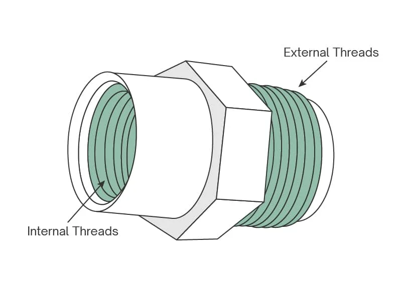
雄ねじと雌ねじの選択は、アンダーカットを離型するという課題のため、金型の複雑さとコストを根本的に決定します。.
あ. おねじ (最も簡単な方法)
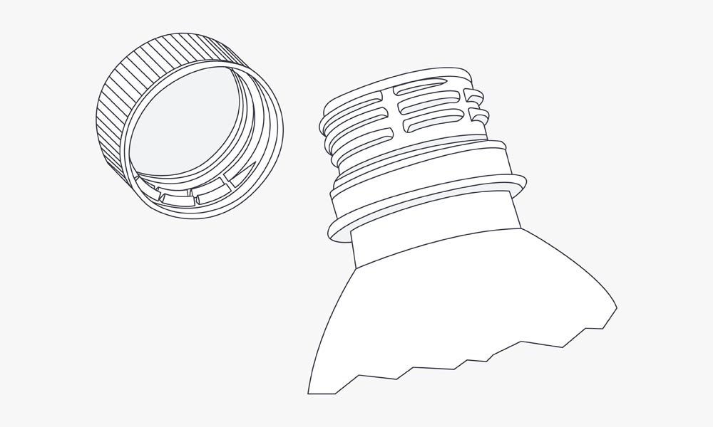
設計の難易度: 比較的簡単. 外部ネジ (ペットボトルのキャップのように) 部品の外周に沿って形成する.
方法: ねじの形状は金型の形状によって直接作成されます。ねじの谷は、 空洞 壁, ねじ山の頂点は コア 壁. 糸自体を型から外すために厳密に言うと動きは必要ありません.
欠点: 別れの行: 糸が金型のパーティングラインをまたぐため, 目に見えるものと触覚的なもの パーティングライン 糸の軸に沿って走ります. 経験豊富な成形業者はバリを軽減できますが、, ラインは永久的な機能のままです, シールや正確なかみ合いに影響を与える可能性があります.
B. 雌ねじ (複雑なアンダーカット方法)
設計の難易度: 大幅に難しくなる. 雌ねじは、パーツをコア ピンに固定するアンダーカットを表します。, 特殊な脱型機構が必要.
主な自動方法: 巻き戻しコア / アンワインダー:
機構: 追加の電動または油圧作動機構がモールドベースに追加されます。. これ 巻き戻しコア (またはネジを緩める機構) コアピンを回転させて完成品から外します 排出される前に.
アドバンテージ: パーティングラインなし スレッド上で, 360 度完璧な糸品質を保証. 短いサイクル時間.
短所: 金型コストが大幅に増加する, 複雑, メンテナンス, そしてセットアップ時間.
二次手動方式: 手動ハンドロード:
応用: 自動化が現実的ではない非常に少量の生産または非常に大規模なスレッドに最適です.
プロセス: 各サイクルの前に、専用のネジ付きコアピンを手動で金型に配置します。. 注射後, 完成したパーツが排出される コアピンが入ったまま. 次に、オペレーターが手持ちツールを使用して、部品からコアのネジを手動で外します。.
短所: 必要 複数のコアピン 再挿入する前に金属コアが冷えるまでの時間を確保するため. サイクルタイムが非常に遅くなり、人件費が高くなる.
完成品のねじの解放方法
完成品のねじの解放方法
適切なリリース方法を選択すると、工具コストのバランスが取れます, サイクル時間, スレッドの複雑さ.
あ. 強制リリース (ストリッピング) – ほとんど使用されない
機構: 型が開きます, そして、エジェクターピンが部品をねじ付きコアピンから押し出します。. スレッドは 伸ばされて剥がされた コアピンの上に.
適用性: 小さなスレッドでのみ実行可能 (例えば, フレキシブルボトルキャップの細かいピッチ) 高い伸び特性を持つ材料を使用 (PEやPPのような).
重要な設計の前提条件:
ねじ山プロファイルには重要な要素を組み込む必要があります ドラフト角度 (テーパー) そして寛大な 半径 (丸み) ねじ山と根元に.
壁の厚さは次のとおりである必要があります 一貫性のある 比較的薄いため、剥離中にプラスチックが割れることなく曲がることができます。.
B. 手動挿入 (引き出し) – 時々使用される
機構: (セクション II.B を参照, ハンドロード方式) サイクル後のコアピンの取り外しはオペレーターの労力に依存します.
トレード・オフ: 初期ツールのコストは低いが、運用コストは最も高い (労働) 最長のサイクルタイム. 人件費がかかるため、プロトタイピングや非常に限定された実行以外では非効率になります。.
C. 全自動巻き戻し - 最も一般的
機構: (セクション II.B を参照, 巻き戻しコア) 専用モーターを使用 (油圧または電気サーボ) 機械の開口シーケンスと同期して、ねじの芯を部品から機械的に回転させます。.
利点: 最短のサイクルタイムと最高のスループットを実現, 大量消費者向け部品に必要.
考慮事項: 可動コンポーネントの複雑さと精度 (歯車, ラック, モーター) 先行投資を大幅に増やす. メンテナンスや金型の修理も専門的で高価です.
重要な設計要素とベストプラクティス
糸の耐久性には材料力学と形状への注意が不可欠です.
あ. ねじのサイズとピッチ
プラスチックねじのルール: プラスチック材料は金属よりもせん断強度が大幅に低い.
おすすめ: 雌ねじは少なくとも維持する必要があります 0.3 インチ (約. 7.6 んん) 直径で. 直径が大きいほど、せん断力に対する接触面積が増加します。.
ピッチの選択: を使用します。 可能な限り粗いピッチ (インチ/mm あたりのねじ山の数が少ない). ピッチが粗いということは、荷重が厚い部分に分散されることを意味します, より強力な糸の根元, 剥離の可能性を減らす.
B. アンダーカット
スレッドとは、 ヘリカルアンダーカット, 部品を金型に固定する.
サイドアクションによる排除: 回転脱型できない外ねじまたは側壁ねじの場合, デザイナーは使用できます カム作動のサイドアクション またはスライド. これらは、アンダーカットをクリアするために、開口方向に対して垂直な金型の一部を後退させます。.
トレード・オフ: 効果的です, サイドアクションにより、初期工具のコストと複雑さが大幅に増加し、サイドアクションが金型本体と接する部分に追加のパーティング ラインが発生します。.
C. 材料の選択
素材の柔軟性, 靭性, 耐薬品性が最も重要です.
めねじの推奨材質 (耐久性):
ABS (アクリロニトリル ブタジエン スチレン): 剛性と耐衝撃性のバランスに優れています.
POM (ポリオキシメチレン, デルリンとか): 優れた強さ, 剛性, そして低摩擦 (繰り返しの組立・分解に最適).
ナイロン (ポリアミド): 高い靭性と耐摩耗性, 耐荷重ねじ山に最適です.
おねじ: 周囲の金型キャビティが均一なサポートを提供するため、材料の選択はそれほど重要ではありません。.
D. 一般的な成形のベスト プラクティス
スレッドの成功は、基本的な射出成形原則の遵守にかかっています。:
抜き勾配角度: 型抜きのためにすべての壁に不可欠; 多くの場合、強制解放方法のためにねじの形状自体に組み込まれます.
一貫した肉厚: 均一な冷却を確保するために重要, 反りを最小限に抑える, ねじ山フィーチャーの周囲の応力集中を防ぎます。.
ラジアス設計: 常に使用してください 半径 角で (糸の根元と頂点) 鋭い角の代わりに, 鋭い角はプラスチックの亀裂の発生や応力破壊を非常に起こしやすいため、.
成形ねじに代わるコスト効率の高い代替品
成形されたねじがコストがかかりすぎる、または複雑すぎることが判明した場合, これらの堅牢な代替案を検討してください:
二次加工でのねじ山加工: 部品はネジなしで成形されています, そして専用の機械 (CNCルーターや旋盤など) 部品が冷えた後にねじを切ります. これにより、加工ステップが追加されますが、金型が簡素化されます。.
タッピンねじ: 小さめのねじに打ち込みながら、独自のねじ山を切断または形成するように設計された金属ねじの使用, ネジなし成形穴. これは安価で効果的ですが、繰り返しの分解には適していません。.
オーバーモールドねじインサート (ヒートセットまたは超音波): 事前に製造された金属インサート (ナッツ) 型に入れられます, または、熱または超音波溶着を使用して成形後に取り付けられます。. これにより、プラスチック部品内に金属糸の強度が得られます。, 頻繁な組み立てでも優れた耐抜け性と耐久性を実現.
結論
成形されたねじ山は価値の高い機能です, しかし、それらを統合するには、応力下での塑性挙動と複雑な工具の動作ダイナミクスについての微妙な理解を必要とします。. ネジの形状を慎重に最適化することにより、, ABSやPOMなどの適切な材料の選択, 正しいリリース機構の選択 (多くの場合、大量の場合は完全に自動化されます), デザイナーは固有の課題を克服できる. 疑わしいとき, 経験豊富なプラスチック射出成形業者に相談することは、ねじ山の完全性のバランスをとるために必要なステップです, サイクル時間, コスト効率の高いツールを提供. お問い合わせ 詳細については.
![]()