
Usinagem CNC, Um processo de fabricação avançado em que a precisão da fabricação de componentes depende do desenho técnico. As máquinas CNC, como desenhos de usinagem, são planos para que suas peças sejam cortadas, perfurado, e moldado a partir de matérias -primas. Engenheiros, maquinistas, e os fabricantes precisam entender esses desenhos técnicos para produzir componentes de acordo com as especificações do projeto.
Este guia explicará desenhos de máquinas, sua estrutura, e sua importância. além disso, Ele lhe dirá como prepará -los para o melhor desempenho de usinagem CNC.
O que são desenhos de usinagem CNC?
Os desenhos de usinagem CNC são detalhados de representações 2D ou 3D de um componente, que são cruciais para fabricação precisa. Esses desenhos técnicos definem dimensões, geometrias, tolerâncias, especificações de materiais, e instruções de usinagem. Eles são usados como plantas para Fresamento CNC, girando, perfuração, e moagem Operações para garantir que maquinistas e máquinas CNC produzam peças precisas e consistentes.
Desenho de usinagem CNC, um método universal de comunicação entre engenheiros, designers, maquinistas, e equipes de qualidade na fabricação moderna. Os desenhos de usinagem contêm detalhes adicionais, como tolerâncias, se encaixa, Explicação de orifícios, acabamentos de superfície, e outros detalhes de fabricação. Esses detalhes complementam a forma da parte de modo que quando usinada, A parte final atende aos requisitos funcionais.
A importância da usinagem de desenhos
Então, Os seguintes parâmetros nos ajudarão a entender o significado da usinagem de desenho:

1. Precisão & Precisão
Desenhos de usinagem dão dimensões de peça, tolerâncias, e acabamentos de superfície exatamente especificados para que não haja ambiguidade. Isso significa que todo componente fabricado estará de acordo com o design, com erros mínimos e inconsistência.
2. Padronização
Permite que maquinistas e engenheiros em todo, DE, e jis. Desenhos técnicos são padronizados para que todo o fabricante, fornecedor, e os inspetores de qualidade têm o mesmo entendimento da intenção do design sem interpretação errônea.
3. Eficiência & Redução de custos
Desenhos de usinagem precisos ajudam:
- Minimizar operações desnecessárias durante a usinagem e os caminhos de ferramentas.
- A fase de redução em larga escala inclui a definição de ferramentas precisas, dimensões, e tolerâncias para prevenir o desperdício de material.
- Isso reduz o tempo de configuração e usinagem e cria ciclos de produção rápidos.
4. Controle de qualidade & Inspeção
As equipes de garantia de qualidade usam desenhos técnicos como uma referência para verificar se a parte final está em conformidade com as especificações do projeto. Esses desenhos são usados por engenheiros que inspecionam peças para:
- Tolerâncias dimensionais
- Requisitos de acabamento da superfície
- Tolerâncias geométricas (GD&T)
Anatomia básica de um desenho técnico de usinagem CNC
O desenho de usinagem CNC consiste em alguns elementos importantes que ajudam o maquinista a entender a fabricação da parte. As diferentes seções do desenho realizam diferentes funções para obter precisão, eficiência, e consistência da produção.
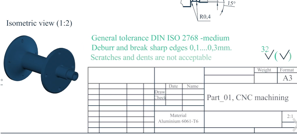
1. Bloco de título
Quase todos os desenhos de usinagem têm seu bloco de título no canto inferior direito. Haverá dados cruciais, como o nome da peça, materiais, escala, Desenho de números, e história da revisão. Nesta secção, engenheiros, maquinistas, e os inspetores de qualidade são capazes de encontrar a versão de desenho e o desenho em que estão trabalhando. Também pode conter o nome do designer, Assinatura de aprovação, e tolerâncias gerais cobrindo o desenho inteiro, a menos que indicado de outra forma.
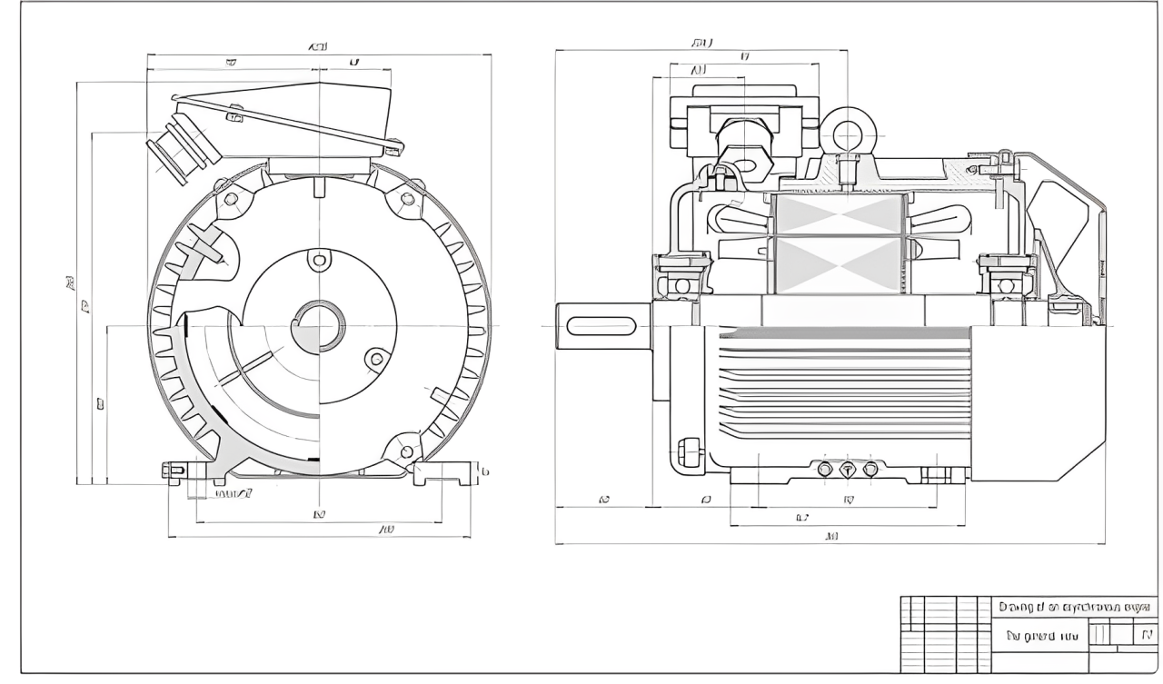
2. Visualizações & Projeções
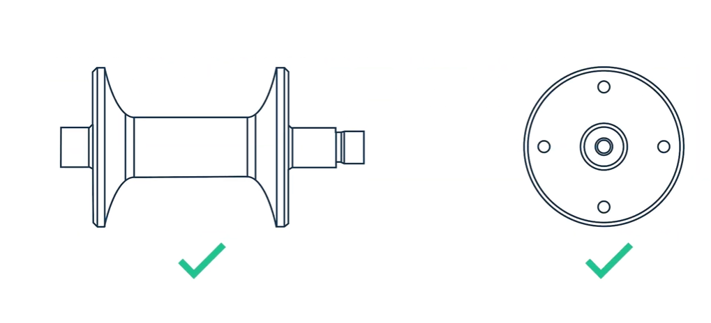
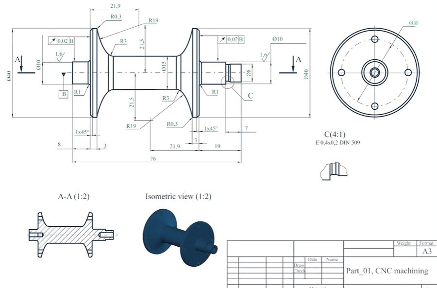
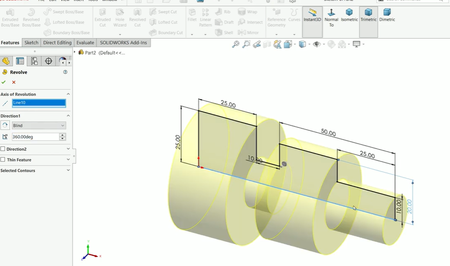
Para representar um componente 3D na forma de 2d, Várias visões e projeções são usadas para representá -las com precisão. A peça é mostrada de diferentes ângulos (vistas ortográficas: frente, principal, lado) para que os maquinistas possam ver a forma e as dimensões da parte. Dá uma representação 3D de como a parte parece na vida real.
Visões seccionais permitem as peças internas que podem não ser discerníveis nas projeções normais, incluindo parâmetros pouco claros como buracos ocultos, cavidades, ou tópicos internos, para ser totalmente articulado.
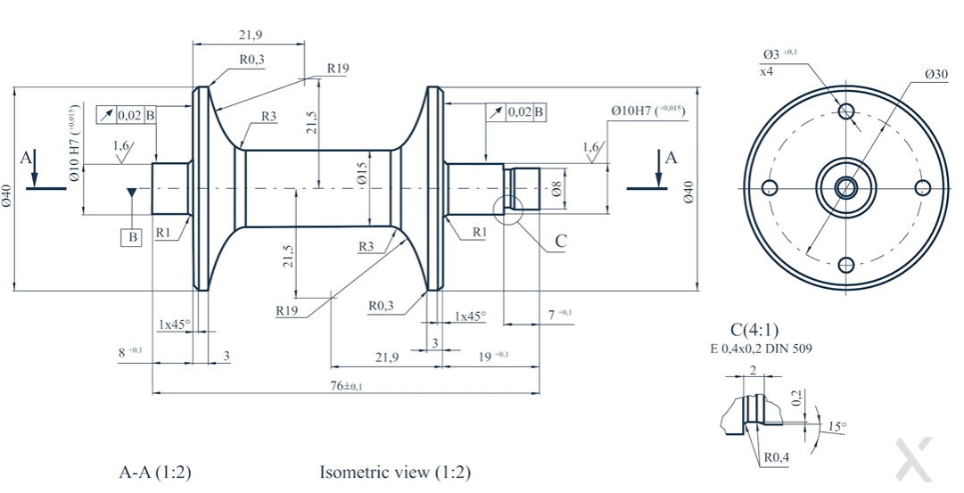
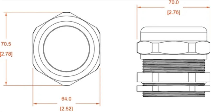
3. Dimensões & Anotações
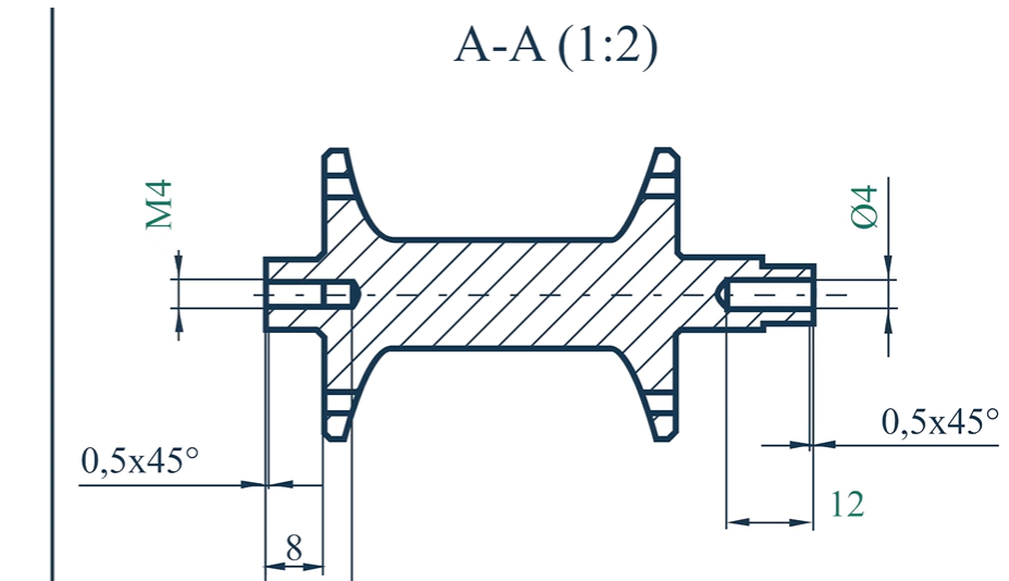
Todas as medidas críticas são definidas nos desenhos de usinagem por dimensões lineares e angulares precisas. Essas especificações especificam os comprimentos, diâmetros, ângulos, e raios e como os chamfers devem ser quando são fabricados com precisão.
Essas anotações fornecem instruções adicionais, como ‘broca a uma profundidade de 10 mm 'ou' bordas de chanfro a 45 ° ', Aquela assim o maquinista sabe todos os detalhes de usinagem. Destacando os aspectos importantes do design, Linhas e chamadas de líderes ajudam a reduzir a desordem no desenho.
4. Tolerâncias & Ajustar
Desenhos de usinagem especificam dimensões aceitáveis por meio de tolerâncias, já que a fabricação perfeita raramente é possível. Dimensões não especificadas têm uma determinada tolerância, Recursos críticos têm tolerâncias específicas que devem atender aos requisitos específicos. É importante decidir se as peças devem ter um ajuste de folga, ajuste de interferência, ou ajuste de transição quando os conjuntos consistem em componentes de acasalamento, como eixo e rolamentos.
5. Símbolos de acabamento superficial
O acabamento da superfície afeta o desempenho, estética, e funcionalidade de uma peça usinada. RA é padrão em engenharia para a média da rugosidade, e a rugosidade da superfície é especificada nos desenhos, conforme indicado por símbolos padrão. A superfície pode ser aproximadamente aceitável se for uma parte estrutural, Mas não é assim para peças móveis ou superfícies de vedação. Com a especificação correta, peças trabalham e atendem aos padrões de qualidade.
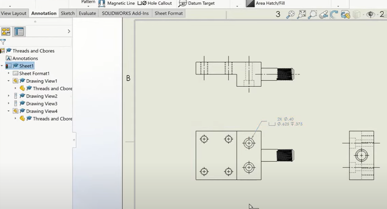
6. Fio & Explosões de orifício
A rosca e os orifícios em um design requerem especificações claras. Os padrões em um desenho de usinagem de giro ou moinho mostram tipo de thread (métrica m8 x 1.25, UNF ¼ ”-20), profundidade do orifício, tom, e outros itens, como contadores ou contra -resíduos. Como resultado, Nenhum buraco ou prendedores tocados introduzirá erros durante a fase de montagem.
7. Lei de Materiais (Bom)
Lei de Materiais (Bom) Inclui todos os materiais, componentes, e submontagens em que a fabricação ocorre. Isso permite que a compra adquira os materiais certos, pois fornece detalhes críticos, como o tipo de material, quantidade de parte, e números de referência. Especificamente para montagens com muitos componentes a serem fabricados e montados exatamente, O nascido é o nosso recurso mais útil.
Um guia gradual para preparar um desenho de usinagem
Vamos discutir as etapas para preparar o desenho de usinagem.
1. Defina os requisitos de projeto
É importante identificar os requisitos funcionais da parte antes que o desenho de usinagem seja criado. Alguns dos requisitos incluem recursos críticos, Seleção de material, tolerâncias, e acabamentos de superfície. Finalmente, Os engenheiros precisam considerar as restrições de usinagem, pois devem considerar que é fabricado com custo e complexidade mínimos.
2. Selecione Tipo de projeção
Projetamos VIDs se o desenho de usinagem no método de projeção de primeiro ângulo ou terceiro ângulo para fácil entender. Projeção do primeiro ângulo (O estilo na Europa) tem a vista superior abaixo da vista frontal. A terceira projeção de ângulo (usado nos EUA) é a vista superior acima da vista frontal. Depois de escolher o padrão de projeção certo, A consistência nos desenhos se torna mais fácil de alcançar.
3. Especificar dimensões & Tolerâncias
Depois disso, Todas as dimensões são adicionadas com fixo, medições explícitas em todas as dimensões. Usando GD&T (Dimensionamento geométrico & Tolerância) apresenta o conceito que se forma, orientação, e a precisão posicional precisa ser definida. A conquista de tolerâncias críticas, que pode incluir desempenho, deve ser destacado para evitar desvios de usinagem.
4. Adicione anotações & Notas
Requisitos de acabamento da superfície, Instruções máquinas, entre outras coisas, notas adicionais, como tratamento térmico ou revestimentos, etc., deve ser incluído. Esses detalhes garantem que a oficina e o fornecedor possa fazer tudo o que é necessário para fabricar esta parte.
5. Validar & Análise
Para garantir a precisão do dimensionamento, ausência de tolerâncias, ou anotações pouco claras, Uma revisão completa do desenho deve ser realizada antes de finalizar. Um desenhado adequadamente, Parte adequadamente validada significa que a peça pode ser fabricada sem interpretação errônea ou reconstrução cara.
Por que os desenhos técnicos ainda são importantes para o fornecimento de peças?
Aqui estão algumas razões pelas quais os desenhos técnicos são importantes para o fornecimento de peças;
- Fabricação: Desenhos são compreensão universal.
- Aplicativo dentro da empresa: Os fornecedores os usam para fornecer estimativas de custo precisas sobre o que custará para fabricar.
- Mudanças podem ser feitas com facilidade de acordo com os desenhos.
- Algumas indústrias precisam ver desenhos técnicos certificados para aprovar peças.
Por que a precisão e a precisão são cruciais nos desenhos de usinagem?
A precisão e a precisão são um dos principais aspectos de qualquer desenho de usinagem CNC;
- Desvios menores podem levar a problemas de montagem ou funcionais, Portanto, você deve impedir a falha da peça de montagem, impedindo a falha de peça.
- Deve garantir a intercambiabilidade: Os componentes devem se encaixar perfeitamente.
- Sabe -se que as máquinas CNC são menos boas apenas porque dependem apenas da precisão de suas instruções sobre como trabalhar.
- Reduz o corte de Capex e o tempo de usinagem: Desenhos precisos minimizam o desperdício de material.
Como adicionar tópicos a um desenho de usinagem
A especificação de orifícios encadeados ou fios externos nos desenhos de usinagem CNC deve ser detalhada para o alinhamento adequado da linha. Um desenho técnico requer seis elementos importantes para adição de threads.
1. Especifique o tipo de encadeamento
Um desenho de usinagem requer identificação do tipo de rosca clara como sua primeira etapa. A criação de recursos rosqueados usa dois padrões fundamentais:
- Um conjunto padronizado de especificações de threads chamadas threads métricas foi estabelecido pelos padrões ISO para uso em toda a Europa e no mercado global.
- Na América do Norte, Os threads USC/UNF aparecem com mais frequência porque cumprem os padrões da ASME.
- A definição do tipo de linha ajuda a usinagem do pessoal a escolher o equipamento de rosqueamento adequado, bem como medir instrumentos em todo o processo de produção.
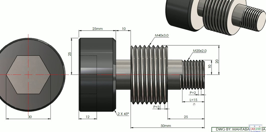
2. Defina o tamanho do thread & Tom
Cada tamanho e tom de threads devem receber uma notação clara para evitar confusão. Uma designação que define os threads compreende dois valores em que o primeiro representa o diâmetro e o segundo indica medição de afinação. Um tópico com m8 × 1.25 dimensões indicam que o diâmetro do fio mede as medidas 8 milímetros, e o tom está em 1.25 milímetros.
- A medição do fio especifica um diâmetro de 8 mm como seu valor nominal.
- A distância do thread é 1.25 milímetros.
- A medição de afinação em threads UNC/UNF é representada através de threads por polegada (TPI) em vez do sistema métrico tradicional. Uma designação de thread de ¼ ”-20 UNC indica que consiste em um diâmetro de ¼ de polegada e 20 Tópicos por polegada.
3. Use símbolos padrão
A notação padrão de encadeamento mantém a padronização porque impede que as interpretações erradas ocorram. As especificações do tópico listadas abaixo precisam ser implementadas:
- ISO 965/1-3 para threads métricos
- ASME B1.1 para threads unificados
- As tolerâncias dos threads, junto com os ajustes e os padrões de classe, são definidos nessas especificações (Acessórios como M8 × 1,25-6h representam fios internos métricos, Enquanto ½ ”-13 unc-2a significa fios externos unificados). As anotações de threads apropriadas possibilitam que os maquinistas entendam o desenho corretamente.
4. Mostrar profundidade & Comprimento da linha
A profundidade do tópico é muito crítica, especialmente para buracos cegos que não passam por toda a parte. O termo m8 × 1.25 – 12 mm de profundidade significa que o fio penetra no material 12 milímetros. Além disso, O desenho deve mostrar se o fio passa por toda a espessura do material ou não. Em raras ocasiões, Uma nota como Thru ou Thread completo pode ser incluído se necessário.
5. Representação transversal
Para garantir clareza, Os fios internos são mostrados por linhas ocultas e fios externos por linhas sólidas, Conforme mostrado em visualizações padrão. Quando tópicos internos devem ser ilustrados em detalhes, como para buracos cegos, as visualizações de peças seccionais devem ser usadas.
Como você adiciona chamadas de orifício em um desenho técnico para CNC?
Existem chamadas de orifício adequadas que devem estar nos desenhos de usinagem CNC para obter especificações de orifício adequadas ao perfurar e tocar e para a colocação adequada na linha de usinagem. Definir recursos do buraco em um desenho técnico corretamente seria algo assim:
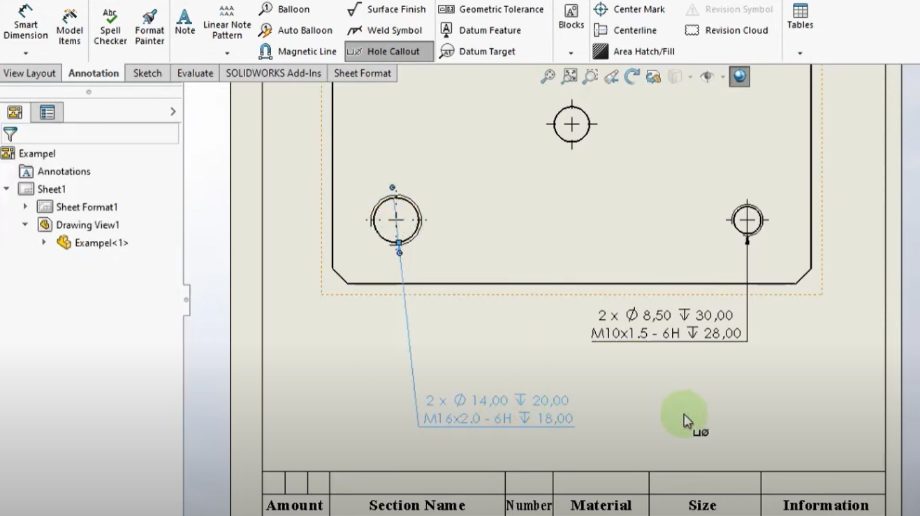
1. Defina o diâmetro do orifício
A coisa mais básica sobre uma chamada de buraco é o seu diâmetro, e isso deve ser expresso usando o ⌀ (diâmetro) símbolo e dimensão. Em outras palavras, No sentido de que em um buraco de ⌀10 mm, O buraco tem um 10 mm diâmetro. Quando um buraco deve ser usinado onde uma tolerância estrita é necessária (ex: ⌀10 ± 0,05 mm), eles devem ser adicionados.
2. Especificar profundidade
Existe a necessidade de marcar, Seja cego ou através, um buraco. O buraco cego não passa pelo material completamente, e sua profundidade é especificada. Isso geralmente é representado como:
- ⌀8 mm ⏤ e 15 mm de profundidade (um buraco cego com 15 mm profundidade).
- Uma notação de orifício a passar é utilizada para os buracos, E isso é feito com um exemplo como ⌀6 mm através, o que significa que os orifícios através da peça devem ser usinados durante toda a espessura da parte.
3. Inclua o tipo de orifício
Além disso, Especificamos orifícios usando diferentes tipos, Então temos mais especificações.
- Contador de ccs pia (CSK) = recesso cônico para acomodar parafusos de cabeça plana na forma ⌀ 10 mm CSK 90 °.
- Furo: ⌀10 mm cb ⌀18 mm × 5 mm de profundidade.
- Os orifícios destinados a roscas de parafuso são chamados (Rosqueado) Orifícios e indicado, por exemplo, por m6 × 1.0 (métrica) ou ¼ ”-20 UNC (tópicos unificados).
4. Posicionamento com GD&T
Para posicionar os orifícios com precisão durante a usinagem de precisão, GD&T (Dimensionamento geométrico & Tolerância) deve ser usado. Os dados e linhas centrais estão satisfeitas, Portanto, a localização dos buracos é relativa. Os desvios aceitáveis na colocação do orifício podem ser especificados como uma tolerância posicional de ⌀10 mm ± 0.1 na posição verdadeira Ø0.05 mmc, por exemplo.
Padrões comuns para desenhos de usinagem
Então, A seguir, são apresentados os padrões comuns que podemos usar para desenho de usinagem:
- ISO (Organização Internacional para Padronização) - Padrões globais de engenharia.
- ASME Y14.5 (Sociedade Americana de Engenheiros Mecânicos) - GD&T Padrões.
- Padrões alemães, amplamente utilizado na Europa, são conhecidos como DIN (Instituto Alemão de Padronização).
- Ele é (Padrões industriais japoneses)- Padrões de fabricação japoneses.
- Bobagem (Padrões britânicos) - Padrões do Reino Unido para desenhos técnicos.
O que é dimensionamento geométrico & Tolerância (GD&T) em desenhos técnicos?
Dimensionamento geométrico & Tolerância (GD&T) é um sistema padronizado para desenho técnico. Ajuda a definir dimensões e tolerâncias específicas para moldar, orientação, tamanho, e localização. além disso, Melhora a fabricação, Aumenta a clareza, e permite que as peças se encaixem e funcionem corretamente em montagens.
Por que é GD&T importante?
- Variação precisa da dimensão parcial: Ele controla a variação no recurso de peça.
- Garante a montagem apropriada, ou seja, ajuste funcional.
- Reduz as tolerâncias rígidas desnecessárias, redução dos custos.
- Reduz erros, retrabalho, e custos de inspeção.
Chave GD&T controles & Símbolos
- Segurança (⏤), Planicidade (▭), Circularidade (○), Cilíndrica (◎).
- Controles de orientação: Paralelismo (∥), Perpendicularidade (⊥), Angularidade ().
- Posição (⌖), Concentricidade (◎ com cruz), Simetria (⇔).
- Controles de Profilems: Pequena de uma linha (∩), Pequena de uma superfície (⌓).
- Controles de redução: Extenção circular (↗), Extenção total (⇈).
Como GD&T é aplicado
- Um quadro de controle de recurso inclui o tipo de tolerância, valor, e referência de dados, e contém GD&T símbolos colocados nele.
- Por exemplo, ⌖ 0.1 | A | B | C significa que um buraco deve ser 0.1 mm de distância dos dados de um, B, e c.
Como as tolerâncias são especificadas em um desenho de usinagem?
As variações aceitáveis das dimensões em peças usadas por CNC são controladas por meio de tolerâncias. Para que eles possam verificar o ajuste e operação adequados do componente. O controle de produção através de notações padrão aparece em desenhos de usinagem para especificar tolerâncias.
Todos os tipos comuns de tolerâncias, juntamente com o uso de símbolos e faixas de valor padrão, aparecer na tabela a seguir.
Tolerâncias comuns em desenhos de usinagem
| Tipo de tolerância | Símbolo / Notação | Valores típicos |
| Tolerância linear | ± x.xx mm (por exemplo., ±0,05 mm) | ~ ± 0,02 mm a ± 0,1 mm |
| Tolerância angular | ± x ° (por exemplo., ± 0,5 °) | ± 0,1 ° a ± 1 ° |
| Tolerância limite | ~ X.xx / Y.yy (por exemplo., 10.00 / 10.05 milímetros) | ~ 10.00 / 10.05 milímetros |
| Tolerância unilateral | X.xx +0.05/-0.00 milímetros | +0.02 / -0.00 milímetros |
| Tolerância bilateral | ~ X.xx ± 0.05 milímetros | ± 0,01 mm a ± 0,1 mm |
| Acabamento de superfície | Ra X.xx µm (por exemplo., Rá 0.8 µm) | ~ 0.2 µm - 3.2 µm |
| Tolerância de ajuste | H7/G6 (Para orifícios/eixos) | H7 (+0.015 / 0.000 milímetros), G6 (-0.005 / -0.015 milímetros) |
Gd comum&T tolerâncias
Dimensionamento geométrico & Tolerância (GD&T) controla a forma de peça e a orientação de peça, bem como posicionamento de parte. O GD principal&T tolerâncias consistem em:
| GD&T símbolo | Tipo | Notação de exemplo |
| ⏤ (Segurança) | Controle de formulário | ⏤ 0.02 milímetros |
| ○ (Planicidade) | Controle de formulário | ○ 0.05 milímetros |
| ⊥ (Perpendicularidade) | Controle de orientação | ⊥ 0.02 mm para datum a |
| ∥ (Paralelismo) | Controle de orientação | ∥ 0.03 mm para datum b |
| ⌀ (Posição verdadeira) | Controle de localização | ⌀ 0.05 mm mmc |
| ∩ (Perfil de uma superfície) | Controle de perfil | ∩ 0.1 milímetros |
Considerações importantes na preparação de desenhos técnicos
Então, A seguir, são apresentados alguns fatos que devemos ter em mente ao preparar desenhos técnicos;
- Mantenha -o simples: Evite tornar os desenhos complexos para que alguém possa entendê -los.
- Siga os padrões da indústria: permanecer por Asme, ISO, ou termos din. A usinabilidade dos recursos é verificada quanto à viabilidade de fabricação.
- Use vistas seccionais e detalhadas: Inclua vistas para os locais dos recursos complexos.
- Especificando rugosidade: Considere quando necessário nos requisitos de acabamento da superfície.
Quais são as aplicações comuns de desenhos de usinagem para usinagem CNC?
Aqui estão alguns dos usos comuns dos desenhos de usinagem CNC em várias indústrias;
- Componentes aeroespaciais de alta precisão para aeronaves e naves espaciais.
- Blocos de motor, Componentes de transmissão, e engrenagens são peças automotivas.
- Dispositivos médicos: Instrumentos cirúrgicos e próteses.
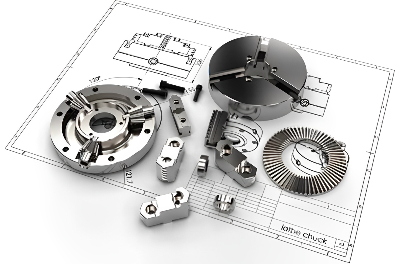
- Maquinaria industrial: Engrenagens, veios, e ferramentas de precisão.
- Caixas, quadros, peças micro-usinadas, etc.: Eletrônicos & Robótica
Conclusão
Para concluir, A fabricação da CNC exige que o Mach se encontre para ser seguido na forma de desenhos de carnings para garantir a precisão, eficiência, e controle de qualidade. Saber como a estrutura deles, padrões, e as melhores práticas funcionam pode ter um enorme impacto em melhorar o processo de usinagem. Isso ajudará a produzir peças melhores e uma produção mais suave. Os desenhos de usinagem são a chave para o sucesso quando você está projetando componentes aeroespaciais ou ferramentas industriais em qualquer projeto de usinagem CNC.
Perguntas frequentes
- Quando a usinagem CNC usaria desenhos de usinagem em vez de modelos 3D?
3D Modelos por si só pode não conter informações vitals, no entanto, como tolerâncias, acabamentos de superfície, e instruções de fabricação, que são fornecidos em desenhos de usinagem.
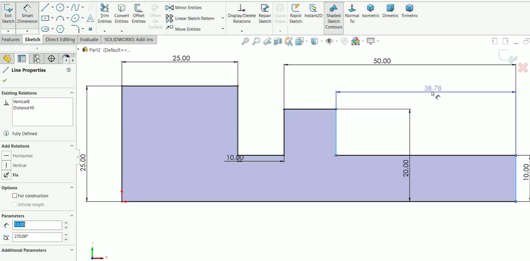
- Como faço para fazer desenhos de usinagem CNC?
O software CAD usado nesta plataforma é o AutoCAD, SolidWorks, Fusão 360, e catia.
- Qual é a diferença entre projeção de primeiro ângulo e terceiro ângulo?
Na Europa, A projeção do primeiro ângulo é usada principalmente enquanto nos EUA, A projeção do terceiro ângulo é a regra. Os dois diferem na colocação de visualizações.
- Como faço para fazer meu desenho de usinagem ladável pelos fabricantes?
Use algumas convenções padrão, e use anotações claras e óbvias, também; Evite detalhes excessivos.
- São desenhos de usinagem usados para CNC e usinagem manual?
Isso implica que os desenhos de usinagem são aplicados nos processos de usinagem CNC e manual.
![]()

