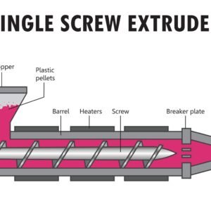
Stampaggio a iniezione is a precise manufacturing process, but its complexity leaves it vulnerable to a variety of defects. Successfully producing high-quality, defect-free plastic parts requires a holistic approach that starts long before the machine ever fires up. By focusing on the core stages—design, utensileria, and material handling—manufacturers can drastically reduce waste, tempo, e costo.
Here are the three critical ways to ensure product success and quality consistency.
Optimize Design through Early Collaboration (Progettazione per la produzione)
The design phase is the most influential point for defect prevention. By adopting a Design for Manufacturability (DFM) mindset and involving the injection molder early, you can preemptively address issues that would be expensive or impossible to fix later.
Critical Design Elements
| Elemento | Quality Impact | DFM Guidelines |
| Spessore della parete | Inconsistent thickness causes uneven cooling, leading to shrinkage variations, deformazione, and internal stress, which manifest as sink marks or bowing. | Aim for uniformità throughout the part. Where thickness changes are necessary, transition them gradually (feathering) to maintain smooth material flow. Pareti più sottili (0.04″–0.150″) require resins with high flow indexes. |
| Radius and Corners | Sharp internal corners act as stress concentration points and impede the flow front, causing short shots, air traps, and excessive residual stress in the material. | Replace sharp corners with generous radii. The internal radius should be at least 0.5 volte lo spessore del muro (R ≥ 0.5t), and the external radius should be Internal Radius + Spessore della parete. This promotes laminar flow and minimizes localized stress. |
| Posizione del cancello | The gate location dictates the flow pattern, fill speed, and distribution of pressure and temperature within the cavity. Poor placement can cause flow lines, linee di saldatura, and short shots. | The gate should typically be placed at the thickest section della parte. This ensures the high-pressure packing phase is most effective where the material volume is greatest. Use multiple gates for very large or complex parts to reduce flow length and pressure drop. |
| Angolo di bozza | Insufficient draft prevents the part from being smoothly ejected, leading to drag marks, scuffing, or even part sticking and breakage inside the mold. | Draft is mandatory on all surfaces parallel to the draw direction. General guidelines suggest a minimum of 0.5 gradi on core features and 1.0 degree on cavity features, increasing to 1.5–3 degrees for parts with deep textures or high-friction resins. |
| Costolette | Ribs enhance structural rigidity and stability without adding excessive mass. Improper rib design, Tuttavia, can create major cosmetic defects. | Rib thickness should be 50% A 66% of the adjacent wall thickness to prevent sink marks on the visible surface. Rib height should be limited to 3x the nominal wall thickness to maintain packing pressure efficiency. Always include radii at the rib base and a generous draft angle (0.5–1.5 degrees). |
The Power of Mold Flow Analysis
Before cutting steel, utilize advanced Mold Flow Analysis (MAE) software. MFA simulates the injection process, predicting issues such as pressure drop, tempo di raffreddamento, shear heating, and potential weld line locations. This virtual modeling allows the designer and molder to iterate and optimize gate location, runner system design, and wall thicknesses, ensuring the tool is built correctly the first time.
Refuse to Skimp on Tool Design and Build Quality
Lo strumento, or mold, is the engine of the injection molding process and often the largest capital investment. A poorly designed or maintained tool is a guaranteed source of recurring defects.
Tooling Considerations for Defect Prevention
Progettazione del sistema di raffreddamento: Inadequate or non-uniform cooling channels lead to temperature variations across the cavity, which is the primary cause of warpage, differential shrinkage, and long cycle times. Optimized cooling circuitry is essential for dimensional stability.
Venting: Trapped air or gas is often compressed during injection, leading to Burn Marks (scorching) O Colpi brevi (preventing fill). The tool must incorporate sufficient Prese d'aria (typically 0.0005″ to 0.001″ deep) at the end of the flow path and around ejector pins to allow gas escape.
Common Tool-Induced Defects
| Difetto | Root Cause in Tooling | Corrective Action |
| Flash | Occurs when molten plastic flows into the parting line or ejector pin clearance. | Caused by: Tool wear/damage (parting line closure failure), insufficient clamp force, or excessive pressure/speed. Action: Refurbish or replace worn mold components (per esempio., core/cavity inserts) and ensure uniform clamp force distribution across the tool face. |
| Short Shot | The plastic solidifies before fully filling the cavity, resulting in an incomplete part. | Caused by: Gate/runner system being too small (high flow resistance) or inadequate venting (air trap resistance). Action: Increase gate/runner size to reduce shear heating and flow resistance, or add/enlarge vents. |
Mastering Material Science and Process Settings
Even with a perfect design and tool, defects can arise from improper material handling or poor processing techniques. Avoiding resin-related issues requires strict adherence to manufacturer specifications.
Addressing Material & Processing Defects
| Difetto | Mechanism and Causes | Process Correction & Material Fixes |
| Discoloration | Esterno: Impurities from dirty equipment (hopper, barrel, throat, mold). Internal: Resin degradation from excessive residence time or melt temperature. | Correction: Implement rigorous cleaning protocols for all material contact areas. Reduce melt temperature or injection pressure to minimize shear heating. Ensure proper drying of hygroscopic resins. |
| Burn Marks | Localized scorching of the plastic, typically black or dark red. | Caused by rapid compression of trapped air (adiabatic heating) or excessive melt temperature. Correction: Reduce injection speed to lower shear heating. Increase clamp force. The most critical fix is ensuring adequate venting nello stampo. |
| Flow Lines | Streaks/patterns that show the history of the flow front. Occur when plastic solidifies at different rates due to varying flow speeds or tool temperatures. | Caused by too low an injection speed or material flowing over sharp features. Correction: Increase injection speed or mold temperature to keep the material fluid longer. Garantire transizioni graduali in part thickness (DFM check). |
| Linee di saldatura | Lines where two separate flow fronts meet and fail to fully fuse. This creates a point of weakness, reducing structural integrity and affecting appearance. | Caused by low temperature or pressure at the meeting point, leading to partial solidification. Correction: Increase melt temperature, increase injection speed, or raise the mold temperature to encourage better molecular diffusion and bonding. Consider relocating the gate to change the flow pattern. |
Material Selection and Handling
The initial choice of resin dictates processing parameters. Hygroscopic materials (per esempio., Nylon, computer, addominali) must be dried to their precise moisture content before processing; otherwise, moisture vaporizes in the barrel, causing structural defects like splay marks E fragilità. Always verify the resin’s official processing data sheet for recommended melt temperatures and drying procedures.
By prioritizing DFM, investing in high-quality tooling, and maintaining strict control over processing parameters and material preparation, manufacturers can dramatically elevate their success rate and consistently produce defect-free, high-performance injection molded plastic parts.
Domande frequenti
Q1: What are Hygroscopic Resins, and why must they be dried before molding?
UN: Hygroscopic resins are plastic materials (such as Nylon, computer, or ABS) that absorb and retain moisture from the surrounding environment. If these materials are not dried to their specified moisture content before injection, the water will rapidly vaporize in the hot, high-pressure barrel. This leads to:
Part Defects: Cosmetic flaws like silver streaks or splay marks on the part surface.
Structural Damage: Hydrolysis of the plastic’s molecular chains, resulting in embrittlement and a significant reduction in strength.
Q2: What is the relationship between the “Parting Line” and “Flash” in mold design?
UN: The parting line is the surface where the two halves of the mold (the core and the cavity) meet and close. Flash is the thin layer of molten plastic that escapes and solidifies in the tiny gaps along the parting line or around the ejector pins due to high injection pressure. The presence of flash usually indicates:
Insufficient Clamp Force: The machine force is not high enough to resist the plastic’s injection pressure.
Mold Wear: The parting surfaces are damaged from long-term use and cannot close tightly.
Q3: Why is a generous Radius emphasized over sharp corners in design?
UN: Sharp corners are a major design flaw in injection molded parts.
Concentrazione dello stress: Sharp corners become focal points for stress during cooling and ejection, which can cause cracking or warpage.
Flow Obstruction: As molten plastic flows around a sharp corner, the flow front separates, potentially creating a stagnant zone or air trap, which can lead to short shots, air marks, or reduced material strength. A radius ensures smooth, uniform material flow and reduces internal stress.
Q4: Besides predicting defects, what are the main uses of Mold Flow Analysis (MAE)?
UN: The primary value of Mold Flow Analysis (MAE) lies in:
Optimizing Process Parameters: Determining the best melt temperature, velocità di iniezione, mantenendo la pressione, and cooling time, thereby reducing cycle time.
Cooling System Optimization: Predicting the temperature distribution of the part, guiding the design and layout of cooling channels to ensure uniform cooling and control warpage.
Material Evaluation: Helping the designer select the best resin from different options, ensuring the chosen material is suitable for the specific part geometry.
Q5: If Weld Lines appear on a part, what is the simplest process adjustment to fix them?
UN: Weld lines occur because the plastic flow fronts meet at a temperature that is too low to allow the molecules to fully interlace and fuse. The simplest process adjustments are to increase the temperature of the plastic or the mold E increase the injection speed.
Increase Temperature: Keeps the plastic in a molten state longer, allowing sufficient time for molecular diffusion and fusion.
Increase Speed: Shortens the fill time, reducing the opportunity for the plastic to cool before the flow fronts meet.
![]()