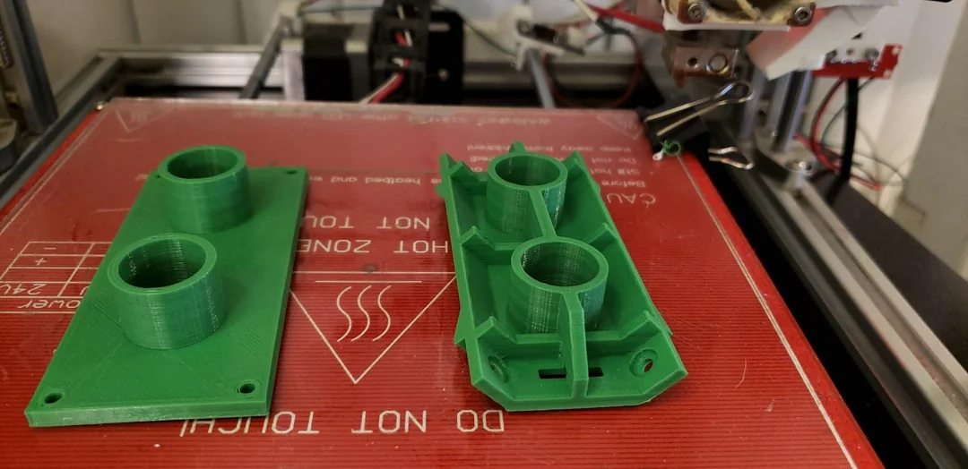
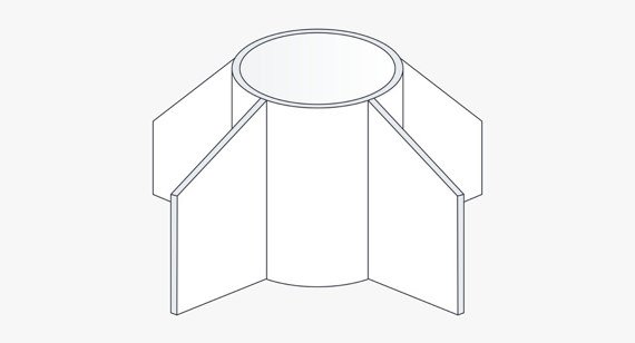
ブログ

ブログHow to Design Ribs for Plastic Parts: Injection Moulding Design Guide

How to Design Ribs for Plastic Parts: Injection Moulding Design Guide

ribs

Ribs are thin, vertical support features commonly found in injection moulded plastic parts. They serve as reinforcement structures that increase a part’s stiffness and strength without adding excessive material or wall thickness.

Properly designed ribs not only enhance mechanical performance but also prevent typical moulding defects such as sink marks, voids, そして 反り. In addition to their structural role, ribs can also be used as aesthetic or functional design elements, helping to improve both appearance and assembly fit.

しかし, rib design must be handled with precision. Incorrect rib proportions or spacing can lead to poor mould filling, longer cooling cycles, or even part failure. This guide explores when to incorporate ribs, how to design them effectively, and the essential best practices for injection moulding.

Why Proper Rib Design Matters

Why Proper Rib Design Matters

Why Proper Rib Design Matters

In plastic part design, maintaining consistent wall thickness is essential to achieving uniform cooling and minimal residual stress. But increasing wall thickness to strengthen a component can lead to unwanted side effects such as sink marks そして 反り.

Ribs offer a smart solution: they provide localized reinforcement without thickening the wall, thereby maintaining manufacturability and reducing material costs. Well-designed ribs can:

Increase bending and torsional stiffness

Prevent part deformation under load

Support mounting bosses or structural joints

Improve impact resistance while reducing weight

逆に, poorly designed ribs—too thick, too tall, or too close—can trap air, cause cooling inconsistencies, or produce visible surface defects.

When to Incorporate Ribs in Your Design

Ribs should be considered during the early design phase, especially in the following scenarios:

Parts requiring structural reinforcement without increasing wall thickness

Large or complex parts that need localized stiffness or dimensional stability

Components under pressure, torsion, or bending 負荷 (例えば, カバー, ハウジング)

軽量部品 where reducing material use is critical for cost efficiency

Enclosures and casings where rigidity and aesthetic smoothness are both desired

Using ribs strategically helps achieve an optimal balance between mechanical performance and manufacturability.

Rib Design Guidelines

Rib Design Guidelines

Rib Design Guidelines

Designing ribs requires careful consideration of geometry, 間隔, and wall ratios. The following guidelines summarize best practices for effective rib design in injection moulded parts.

Rib Height

Rib height directly affects part stiffness, but excessive height can cause filling issues and stress accumulation.

Recommended: Rib height should not exceed 3× the nominal wall thickness.

なぜ: Taller ribs are prone to warpage, voids, and poor mould filling.

ヒント: Use multiple short ribs instead of a single tall one for better strength distribution.

Rib Thickness

Rib thickness is one of the most critical parameters in avoiding sink marks.

Recommended: The rib thickness should be 40–60% of the nominal wall thickness.

なぜ: Thicker ribs cool slower than surrounding areas, leading to shrinkage and visible surface depressions.

ヒント: Always maintain smooth transitions from the rib to the base wall to ensure uniform cooling.

Rib Radii

The base of a rib should never form a sharp corner.

Recommended: Add a radius equal to 0.5–1× the nominal wall thickness at the rib base.

なぜ: Rounded corners distribute stress evenly and prevent cracking during use or ejection.

ヒント: Match rib radius with the adjoining wall radius to maintain consistent flow paths.

Rib Spacing

When multiple ribs are used, spacing plays a major role in both moulding performance and cooling behavior.

Recommended: Ribs should be spaced 2–3× the nominal wall thickness apart.

なぜ: Too-close ribs restrict resin flow and trap heat, increasing the risk of sink marks and extended cycle times.

ヒント: For large panels or covers, distribute ribs symmetrically to balance stress and cooling rates.

Rib Draft Angle

A proper draft angle ensures that the part can be ejected smoothly from the mould without sticking or scuffing.

Recommended:minimum draft of 0.5° per side should be applied to all ribs.

Exception: Crush ribs used for interference fits may have no draft.

ヒント: For deep ribs, increase draft slightly (up to 1°) to ensure clean ejection.

Summary of Rib Design Rules

パラメータ ガイドライン
Rib Height ≤ 3× nominal wall thickness
Rib Thickness ≤ 60% of wall thickness
Rib Radius 0.5–1× wall thickness
Rib Spacing 2–3× wall thickness
Rib Draft ≥ 0.5° per side

Injection Moulding Best Practices for Rib Design

Even if rib geometry follows the above ratios, additional design practices are crucial to ensure smooth injection moulding and high-quality parts.

Avoid Excessive Ribbing

Too many ribs increase mould complexity, prolong cycle time, and make ejection more difficult. その代わり, apply ribs strategically where they have the greatest structural benefit.

Ensure Adequate Venting

Air traps often occur near rib bases or intersections. Proper venting in these areas prevents defects such as short shots, 火傷, そして splay.

Maintain Uniform Wall Thickness

Ribs should blend into walls with smooth transitions to maintain consistent material flow and cooling. Avoid sudden thickness jumps, それにつながる可能性があります sink marks または voids.

Avoid Abrupt Transitions from Thin to Thick

Design gradual changes between thin and thick regions to minimize internal stress and shrinkage differentials.

Align Ribs with Load Paths

When possible, align ribs in the direction of the applied load or bending moment for maximum reinforcement efficiency.

Design for Manufacturing (DFM) 考慮事項

Before mould fabrication, every rib feature should be validated through DFM (Design for Manufacturing) 分析.

Key DFM checkpoints include:

Verification of rib thickness and draft angles

Assessment of rib placement for mould filling and venting

Simulation of cooling uniformity and shrinkage

Detection of potential ejection and tooling challenges

To obtain accurate feedback, export your 3D CAD files in STEP format and submit them to a trusted manufacturing partner. 最高の精度 (or similar service providers), engineers review your design and provide both a quotation and detailed DFM report, ensuring your rib designs are production-ready.

結論

Ribs are fundamental elements in plastic injection mould design, offering a smart way to enhance strength and stiffness without sacrificing weight or manufacturability. By adhering to standard rib design guidelines—controlling height, 厚さ, 間隔, and draft—you can significantly improve product performance and moulding consistency.

Thoughtful rib design not only prevents defects like sink marks and warping but also reduces cycle times, improves part appearance, and enhances long-term durability.
When combined with proper DFM review, optimized rib geometry leads to high-quality, cost-effective plastic components suited for mass production.

Ready to improve your part design?
Follow these rib design rules and submit your CAD models for a free design-for-manufacturing review and instant quotation.

読み込み中

プラスチック射出成形材料
前の投稿

射出成形材料選択ガイド

次の投稿

18 機械加工のメリット

返信を残す

あなたのメールアドレスが公開されることはありません. 必須フィールドは、マークされています *

Let's Start A New Project Today

今すぐお問い合わせを送信してください

    入力を開始すると、探している投稿が表示されます.