
Dans le monde de l'ingénierie, La précision et la cohérence ne sont pas négociables. Chaque partie doit s'aligner, ajuster, et fonctionne exactement comme prévu. Pour y parvenir, Les ingénieurs comptent sur un concept fondamental appelé données. Si vous êtes usinage un arbre de vitesse, Alignement des pylônes de pont, ou inspecter un composant aérospatial, Les données fournissent le fondement invisible mais essentiel pour toutes les mesures et tolérances.
Ce guide complet plonge profondément dans le concept de données, leurs types, notations, candidatures, et rôle critique dans l'ingénierie et la fabrication modernes.
Que sont les données en ingénierie?
UN données est un point de référence théorique, doubler, ou plan utilisé pour établir un système de coordonnées pour la mesure et la conception. Considérez-le comme un point zéro ou un emplacement de départ que les ingénieurs utilisent pour s'assurer que chaque mesure d'une pièce est reproductible, cohérent, et standardisé.
Sans dates, Il n'y aurait aucun moyen de garantir que les composants produits dans différentes usines - ou même à différents jours - s'aligneraient et s'adapteraient correctement à l'assemblage.
Types de données
Date principale
La donnée principale est la première et la plus importante référence. Il se compose généralement de trois points de contact qui se trouvent sur une surface plane, formant un plan stable. Cet avion restreint le mouvement dans trois directions: traduction le long du x, Oui, et axes Z.
Cas d'utilisation: Surfaces d'accouplement entre les assemblages mécaniques, comme une surface de boîtier de transmission dans un moteur automobile.
Datums secondaires
La donnée secondaire est utilisée après la création du primaire. Il fournit deux autres points de contact - formant une ligne perpendiculaire à la donnée primaire et restreint le mouvement dans deux directions supplémentaires (généralement rotation).
Cas d'utilisation: La surface latérale d'un support qui s'aligne orthogonalement sur la base.
Datus tertiaires
La donnée tertiaire complète le cadre de référence de la référence (DRF) avec un dernier point de contact. Il est perpendiculairement aux données primaires et secondaires et contrôle le dernier degré de liberté restant.
Cas d'utilisation: Un petit boss ou une fonctionnalité utilisée pour l'alignement final dans l'assemblage des composants.
Indiquer, Doubler, et les données d'avion
Les données peuvent également être classées par leur forme physique:
Date de point: Représenté par un seul point (point ou croix), Utilisé pour référencer les petites fonctionnalités.
Date de ligne: Références droites idéales pour les pièces ou les bords cylindriques.
Date d'avion: Surfaces plates utilisées comme bases stables pour mesurer ou aligner d'autres caractéristiques.
Axe et données de plan centrales
Date d'axe: Une ligne médiane théorique à travers une caractéristique cylindrique ou ronde. Il est utilisé pour mesurer la concentricité ou la rotation.
Date de l'avion centrale: Un plan médian entre deux surfaces parallèles, Idéal pour les pièces symétriques.
Les deux sont essentiels dans la mesure des parties rondes ou symétriques où l'alignement central est crucial.
Notation et symboles de la référence
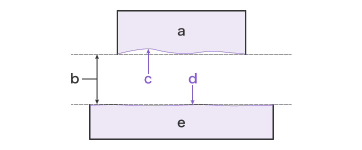
une partie cible; B Date (conceptuel); C. (plan ou ligne de la pièce); D Fonction de référence simulée (plan ou ligne d'une plaque de surface ou d'une jauge); E Plaque de surface, jauge, mandrin, etc..
La compréhension des symboles de la référence est vitale pour lire correctement les dessins d'ingénierie.
Symbole de fonction de référence
Une majuscule dans un cadre carré (par exemple., UN, B, C) connecté par une ligne de leader à la fonctionnalité. Cela identifie la surface ou la fonctionnalité est la fonction de référence.
Symbole de référence de la référence
Lettres placées dans des boîtes ou des triangles sur le cadre de contrôle des fonctionnalités. Ceux-ci indiquent l'ordre de priorité sur les réseaux (par exemple., UN | B | C).
Symbole cible de la référence
Un cercle divisé, avec la moitié inférieure montrant une lettre et un numéro (par exemple., A1, A2), utilisé pour identifier les points discrets, lignes, ou zones sur des surfaces irrégulières.
Symbole de point de référence
Une simple croix (+) ou point (•) sur un dessin pour identifier un point de référence spécifique.
Ces symboles fournissent des indices visuels qui définissent comment une partie doit être mesurée et alignée pendant l'inspection ou l'assemblage.
Caractéristiques de la réduction vs. Date

Caractéristique de date: Le réel, Partie physique d'un composant utilisé pour établir une donnée, comme la surface d'une bride, le centre d'un trou, ou l'axe d'une épingle.
Données: Le plan théorique, indiquer, ou axe dérivé d'une fonction de référence.
Par exemple, le centre d'un trou est la fonction de référence; le axe traversant le centre est la donnée.
Applications des données
Avantages de contrôle de la qualité
Les données sont le fondement de inspections reproductibles et précises. Des outils comme coordonner les machines de mesure (CMMS) Utilisez des cadres de référence de référence pour vérifier que les pièces sont conformes aux spécifications - la cohérence de l'inscription entre les lots.
Utilisations en automobile et en aérospatiale
Dans l'aérospatiale, Les données aident à assurer un assemblage précis des lames de turbine, peaux de fuselage, et composants du train d'atterrissage. En ingénierie automobile, Ils sont essentiels pour assurer l'alignement des blocs moteurs, systèmes de suspension, et assemblages de transmission.
Rôle dans la fabrication
Datums Simplifier la conception et les processus de conception du luminaire. Ils s'assurent que chaque pièce est produite avec une orientation et un positionnement cohérents - réduisant les retouches, Améliorer l'ajustement, et accélérer la production.
Applications de génie civil
Les données sont utilisées pour établir élévation, alignement, et emplacement Dans des projets à grande échelle comme les routes, ponts, tunnels, et bâtiments. Les arpenteurs les utilisent comme lignes de base pour la cartographie et la mise en page.
Ciblage de données pour les pièces irrégulières
Des formes complexes comme les pièces moulées ou les pièces forgées peuvent ne pas avoir des surfaces plates ou symétriques. Dans ces cas, cibles de référence (points ou zones de la part) sont utilisés pour définir des emplacements de mesure stables. Ceci est essentiel dans des industries comme l'aérospatiale où même les pièces irrégulières ont besoin de précision.
Conclusion
La maîtrise de l'utilisation des données est essentielle en ingénierie, fabrication, et assurance qualité. Ils fournissent un langage de mesure partagé dans toute la conception, production, et les équipes d'inspection.
Que vous conceviez un composant de moteur à réaction ou que vous construisiez un tunnel, Les données gardent tout aligné, contrôlé, et mesurable. Ce sont les héros méconnus qui rendent possible l'ingénierie précise.
FAQ
Q: Quelle est la différence entre une donnée et une fonction de référence?
Une donnée est une référence idéalisée (indiquer, doubler, ou plan), tandis qu'une fonction de référence est la géométrie de partie réelle utilisée pour établir cette référence.
Q: Pourquoi utiliser un cadre de référence de référence (DRF) en gd&T?
Le DRF combine le primaire, secondaire, et des réseaux tertiaires pour former un système de coordonnées qui assure une mesure et une tolérance précises.
Q: Quelle est la différence entre un axe de données et un point ou un plan de référence?
Un axe de données est une ligne centrale pour les caractéristiques cylindriques contrôlant plus de degrés de liberté; Les points et les plans sont des références plus simples qui contrôlent moins.
Q: Les données peuvent-elles être appliquées aux surfaces incurvées ou irrégulières?
Oui. Les ingénieurs utilisent cibles de référence sur des formes complexes pour créer des systèmes de mesure stables et reproductibles.
![]()

