
Quando si progettano parti per stampaggio a iniezione, uno dei dettagli più trascurati ma critici è il angolo di bozza. Un angolo di sformo non è semplicemente una caratteristica estetica o opzionale: influisce direttamente sulla capacità di rilascio di una parte dallo stampo, quanto durano i tuoi utensili, e quanto è coerente il tuo ciclo di produzione.
Senza pescaggio sufficiente, le parti stampate possono aderire alla cavità dello stampo, causando segni di trascinamento, deformazione, o addirittura danni da muffa. Questi problemi portano a tempi di ciclo più lunghi, riparazioni costose degli strumenti, e qualità ridotta delle parti. Per efficiente, produzione di alta qualità, comprendere e applicare gli angoli di sformo corretti è essenziale.
Questa guida spiegherà cos'è un angolo di sformo, perché è fondamentale, e come candidarsi bozza delle migliori pratiche di progettazione per prestazioni ottimali dello stampo e qualità delle parti.
Che cos'è un angolo di sformo?
Che cos'è un angolo di sformo
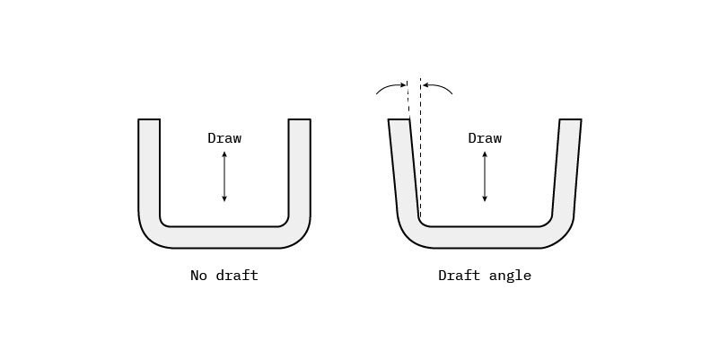
UN angolo di bozza è il rastremazione applicata alle pareti verticali di una parte stampata a iniezione per facilitarne il rilascio dallo stampo. In genere viene misurato gradi (°) e garantisce che lo stampo si apra, le parti non si trascinano né si sfregano contro le pareti della cavità.
Pensatela in questo modo: se le pareti di una tazza modellata fossero perfettamente diritte, la parte creerebbe un vuoto o un blocco per attrito contro lo stampo. Un angolo di sformo allarga leggermente la parte superiore, rendendo più facile l'espulsione pulita della parte.
In breve, angoli di tiraggio:
Ridurre l'attrito tra la parte e lo stampo
Ridurre al minimo la forza di espulsione
Prevenire danni alla superficie
Consenti più velocemente, cicli produttivi più affidabili
Vantaggi dell'incorporazione degli angoli di sformo
L'inclusione degli angoli di sformo nella progettazione della parte comporta numerosi vantaggi, sia per l’efficienza produttiva che per la qualità del prodotto:
Riduce la forza di espulsione e l'attrito tra lo stampo e la superficie del pezzo
Previene lo sfregamento, segni di trascinamento, o deformazione, garantendo una finitura più liscia
Aumenta la longevità della muffa riducendo al minimo l'usura durante l'espulsione
Velocizza i tempi del ciclo consentendo un più facile rilascio dello stampo
Migliora la consistenza delle parti attraverso grandi cicli di produzione
Riduce i tassi di scarto e scarto, riducendo i costi complessivi di produzione
In breve, l'aggiunta di una bozza migliora non solo il estetica e precisione dimensionale delle tue parti ma anche il Efficienza dei costi dell'intero processo.
Regole dell'angolo di sformo e migliori pratiche
1. Angolo di sformo minimo: 1.5° al 2°
Un minimo di 1.5°–2° è generalmente consigliato per pezzi con profondità dello stampo fino a 2 pollici (50 mm).
Ciò è sufficiente per evitare segni di trascinamento e consentire un'espulsione affidabile.
A Grace Harness, generalmente consigliano i nostri ingegneri 2° o più per fornire un margine di sicurezza, soprattutto quando la superficie finisce, geometrie complesse, o sono coinvolte tolleranze strette.
2. Progetto di direzione: Verso l'apertura dello stampo
Applicare sempre la bozza nella direzione del movimento dello stampo. Quando lo stampo si apre, il lato della cavità si sposta verso l'alto o verso l'esterno, quindi la bozza dovrebbe seguire quella direzione.
Per esempio, in una parte cava a forma di scatola, IL l'apertura superiore dovrebbe essere leggermente più ampia rispetto al fondo. Ciò garantisce che quando la parte viene espulsa, non si attacca al nucleo o alle pareti della cavità.
3. Aggiungere 1° sformo per pollice di profondità
All'aumentare della profondità di un elemento stampato, lo stesso vale per la superficie e l'attrito durante l'espulsione.
Una buona regola pratica è: aggiungere 1° di tiraggio per ogni 25 mm (1 pollice) di profondità della cavità.
Esempio:
Se la tua caratteristica è 75 mm profondo, dovresti includere almeno 3° di spoglia per un'espulsione regolare e un'usura minima dell'utensile.
4. Aumenta lo sformo per superfici strutturate o incise
Superfici strutturate, come quelli con mascherino, grano, o finiture in pelle, aumentare l'attrito durante l'espulsione. Per compensare, aggiungere uno sformo aggiuntivo in base alla ruvidità della superficie.
| Tipo di finitura superficiale | Bozza consigliata |
| Superficie liscia o lucidata | 1°–2° |
| Trama leggera | 3° |
| Tessitura media | 4° |
| Texture pesante o incisione profonda | 5° o più |
Mancia: Conferma sempre la profondità della trama (misurato in micron) con il fornitore dello stampo per determinare il corretto incremento di spoglia.
5. Tenere conto del ritiro e della flessibilità dei materiali
Materie plastiche diverse si comportano diversamente mentre si raffreddano. Materiali che restringersi di più Volere afferrare lo stampo più stretto, richiedendo un angolo di sformo maggiore.
| Materiale | Pescaggio minimo (°) | Bozza consigliata (°) | Note |
| Nylon (PAPÀ) | 0° | 1° | Flessibile, si rilascia facilmente |
| Polietilene (PE) | 0.5° | 1.5° | Basso ritiro, buon flusso |
| PVC | 0.5° | 1.5° | Rigido, necessita di un leggero tiraggio |
| Polipropilene (PP) | 1° | 2° | Restringimento moderato |
| Policarbonato (computer) | 1.5° | 2° | Fragile, beneficia di un pescaggio più elevato |
Regola generale:
Maggiore è il ritiro o la rigidità del materiale, IL maggiore è il tiraggio hai bisogno.
6. Applica sformo a tutte le funzioni a contatto con lo stampo
Il tiraggio non è limitato ai muri esterni:ogni caratteristica modellata i contatti con lo stampo devono avere una brutta copia per garantire il corretto rilascio.
| Tipo di funzione | Bozza consigliata (°) |
| Costolette | ≥ 0,5° |
| Diametro interno del boss | ≥ 0,25° |
| Diametro esterno del boss | ≥ 0,5° |
| Soffietti o feritoie | ≥ 1° |
Questo vale per nuclei interni, cavità esterne, e caratteristiche di rinforzo come nervature che rafforzano le pareti sottili.
7. Sformo fronte-retro per parti simmetriche
Per le parti che si dividono lungo la linea centrale (come cilindri o cupole), lo sformo deve essere applicato su entrambi i lati della linea di giunzione.
Ciascun lato dello stampo ha la propria direzione di rilascio, quindi entrambe le superfici necessitano di angoli di sformo adeguati per evitare che si attacchino.
8. Pescaggio minimo: Non scendere mai sotto gli 0,5°
Anche nei casi in cui sono necessarie pareti verticali quasi diritte, dovresti includere almeno 0,5° di pescaggio su tutte le facce verticali.
Se il tuo progetto richiede assolutamente una geometria diritta, consultare il produttore dello stampo per vedere se la consistenza, lucidatura, o le regolazioni della linea di giunzione possono aiutare a compensare.
Ricordare: qualche bozza è sempre meglio di niente.
Errori di progettazione comuni da evitare
Dimenticarsi di applicare lo sformo alle pareti interne o alle nervature
Progettazione di modelli CAD senza bozza integrata (causando rilavorazioni successive)
Non si regola la struttura o lo spessore del rivestimento
Ignorando il comportamento di ritiro del materiale
Complicare eccessivamente la geometria della parte senza considerare la direzione di rilascio dello stampo
La bozza è un requisito, Non un suggerimento
La bozza è un requisito, Non un suggerimento
I progettisti spesso si concentrano sulla geometria della parte, estetica, o funzionalità trascurando la producibilità.
Tuttavia, non importa quanto sia perfetto il tuo progetto su CAD, non può essere modellato in modo efficiente senza una corretta bozza.
Un progetto inadeguato porta a:
Parte attaccata o strappata
Danni alla muffa e tempi di inattività
Scarse finiture superficiali
Aumento dei costi di scarto e manutenzione
Dai sempre la priorità alla bozza nelle prime fasi di progettazione: è una parte essenziale Progettazione per la produzione (DFM).
Suggerimenti avanzati da Massima precisione
Integra la bozza in anticipo:
Aggiungi angoli di sformo durante la fase di modellazione CAD. Ciò garantisce che il tuo prototipo o stampa 3D rifletta già una geometria modellabile realistica.
Eseguire l'analisi DFM:
Prima della realizzazione dello stampo, eseguire un controllo DFM per identificare aree di bozza insufficienti o di rilascio complesse. Il nostro team offre analisi DFM gratuite per aiutarti a ottimizzare la progettazione degli stampi.
Collabora con i produttori di utensili:
Discutere la direzione della bozza, posizionamento della linea di giunzione, e metodi di espulsione anticipati. I produttori di utensili possono spesso suggerire piccoli aggiustamenti che migliorano notevolmente la producibilità.
Prova con prototipi:
Utilizza la stampa 3D o strumenti software per convalidare la bozza del tuo progetto prima di impegnarti nella produzione su vasta scala.
Riepilogo rapido dei riferimenti agli angoli di sformo
| Fattore | Bozza consigliata (°) |
| Superficie liscia | 1°–2° |
| Trama leggera | 3° |
| Trama pesante | 5°+ |
| Profondità bassa (<25 mm) | 1°–2° |
| Cavità profonda (>75 mm) | 3°–4° |
| Materiale PP o PC | 2° |
| Nylon o plastica flessibile | 1° |
| Costolette / Boss | 0.25°–0,5° |
Conclusione
Gli angoli di sformo possono sembrare un piccolo dettaglio di progettazione, ma il loro impatto sulla producibilità è enorme. Proteggono il tuo stampo, migliorare l'aspetto della parte, e minori costi di produzione.
Per uno stampaggio a iniezione di successo:
Aggiungere almeno 1,5°–2° bozza ove possibile
Aumentare per parti strutturate o profonde
Tenere conto del materiale e della geometria
Applicare lo sformo a ogni caratteristica a contatto con lo stampo
In caso di dubbio, Ricordare: più bozza = meno problemi.
Per saperne di più:
Tutto sulle basi dello stampaggio di iniezione di plastica
Tipi di stampi per iniezione: Categorie, Caratteristiche, e applicazioni industriali
Costole di plastica per il design di iniezione: Best practice e linee guida
Domande frequenti
1. Perché l'angolo di spoglia è importante nello stampaggio a iniezione?
Gli angoli di sformo sono essenziali per garantire un'espulsione regolare del pezzo dallo stampo. Senza progetto, le parti possono attaccarsi, ordito, o danneggiare lo strumento, con conseguenti tempi di inattività costosi e prodotti di scarsa qualità.
2. Cosa succede se progetto una parte senza bozza?
Una parte senza angolo creerà un elevato attrito durante l'espulsione, spesso causando segni di trascinamento, distorsione, o anche parti incrinate. Inoltre aumenta l'usura degli utensili, che riduce la vita dello stampo e aumenta i costi di manutenzione.
3. Quanto sformo dovrei aggiungere per le superfici strutturate?
Per parti testurizzate o con finitura granulosa, aumentare l'angolo di sformo di 1°–2° oltre il valore base. Potrebbero essere necessarie superfici molto strutturate fino a 5° o più a seconda della profondità del disegno.
4. L'angolo di sformo influisce sull'aspetto della mia parte?
SÌ, ma positivamente. Una bozza adeguatamente progettata garantisce una finitura più liscia, meno segni, e colore o struttura costanti dopo lo stampaggio. Visivamente, la differenza tra 1° e 2° è appena percettibile ad occhio nudo.
5. Posso applicare zero draft per ragioni estetiche?
Sebbene possibile in rari casi, è rischioso. Se devi usare zero draft (per esigenze puramente visive), il produttore di stampi potrebbe utilizzare rivestimenti o sistemi di espulsione speciali, ma ciò aumenta i costi e la manutenzione degli utensili. Anche 0.5° bozza è altamente raccomandato come minimo.
6. Quando dovrei aggiungere la bozza nel processo di progettazione?
Aggiungi la bozza il prima possibile nel file Fase di progettazione CAD. Applicarlo successivamente può portare a conflitti di geometria, rielaborazione, e costosi ritardi prima dell'attrezzaggio. L'integrazione della bozza fin dall'inizio garantisce un flusso di lavoro dalla progettazione alla produzione più rapido.
![]()
2 pensieri su "Guida alla progettazione dell'angolo di sformo & Best practice: Come progettare per un migliore rilascio dallo stampo”