



射出成形の欠陥を防ぐには、機械の設定を変更するだけでは不十分です. 互換性のある部品形状が必要です, メンテナンスされたツール, correctly prepared resin, and a validated process. Start by identifying the symptom and its pattern. Then test the suspected cause and verify that your correction preserves dimensions, 外観, および機能.
What Causes Injection Molding Defects?
Injection molding defects usually involve interactions between part design, 素材の状態, ツーリング, and processing.
A sink mark can involve local thickness and inadequate packing. A short shot can involve restricted flow, trapped air, or inconsistent material delivery. The same visible symptom can therefore require different corrections.
Separate cosmetic acceptance from functional acceptance. A visible weld line may meet the drawing, while an internal void may compromise performance without obvious surface evidence.
BASF’s injection molding troubleshooter separates multiple defect categories and possible mechanisms. Use the selected resin grade’s guidance alongside your production evidence.
Before changing settings, record where the defect occurs, which cavities show it, and when it first appeared.
Which Common Defects Should You Identify First?
Classify the defect by its physical appearance and location before choosing a diagnostic path.
Use this table to organize the investigation. The suspected causes are hypotheses, not diagnoses from appearance alone.
| 欠陥 | What You See | Start By Checking |
| Short shot | Missing material or incomplete edges | Filling consistency, pressure limits, flow restrictions, and venting |
| フラッシュ | Thin excess plastic at a tool gap | Shutoff condition, tool closure, and cavity pressure |
| Sink mark | Local surface depression | Thick features, packing access, and gate sealing |
| Internal void | Cavity inside the molded wall | Section geometry, パッキング, and whether gas is involved |
| 反り | Bowing, twist, or loss of shape | Cooling balance, 収縮, 向き, そして排出 |
| ウェルドライン | Line where flow fronts meet | Flow pattern, meeting conditions, and functional strength |
| Burn mark | Local darkening, often near trapped gas | Vent condition, filling sequence, and material degradation |
| Splay | Silver or pale streaks | 水分, volatiles, air entrainment, and thermal history |
| ジェッティング | Snake-like flow trace near entry | Gate entry direction and initial melt velocity |
| Ejection damage | Scuffs, 美白, or cracks after release | 下書き, 表面状態, サポート, and release timing |
For appearance-focused acceptance, distinguish this prevention workflow from a surface-finish specification. Define lighting, 視聴条件, and approved limit samples where relevant.
How Can Part Design Prevent Defects?
Design for consistent filling, パッキング, 冷却, and release before the mold is manufactured.
A narrow operating window may hide a design weakness during sampling. It can become difficult to maintain across normal production variation.
Control Local Thickness
Review thick intersections around ribs, 上司, とコーナー. Core out unnecessary mass where the functional design permits.
Use gradual transitions when wall thickness must change. Do not apply a single wall thickness or rib ratio to every resin and surface requirement.
Autodesk explains that sinks commonly occur near thick sections and opposite ribs or bosses. その sink-mark and void guidance also warns that one correction can introduce another problem.
Review Gates And Meeting Fronts
Choose an entry location that supports packing without putting a vestige on a critical surface. Check where melt divides around holes and meets again.
Adding gates can reduce flow distance but introduce additional meeting fronts. Evaluate the trade-off rather than assuming more gates always improve quality.
弊社の injection molding gate guide to review gate position, サイズ, and sample acceptance.
Design For Release
Provide suitable draft and account for texture, draw depth, and shrinkage onto cores. Specify where ejector contact marks are acceptable.
Avoid concentrating release force on weak walls. Check whether the part can leave the tool without dragging across a functional surface.
Use Simulation To Compare Alternatives
Flow and cooling analysis can help compare gate locations, thickness changes, and likely distortion. Results depend on material data and model assumptions.
Use predictions to plan trials. Do not treat simulation as proof that the production part will meet every requirement.
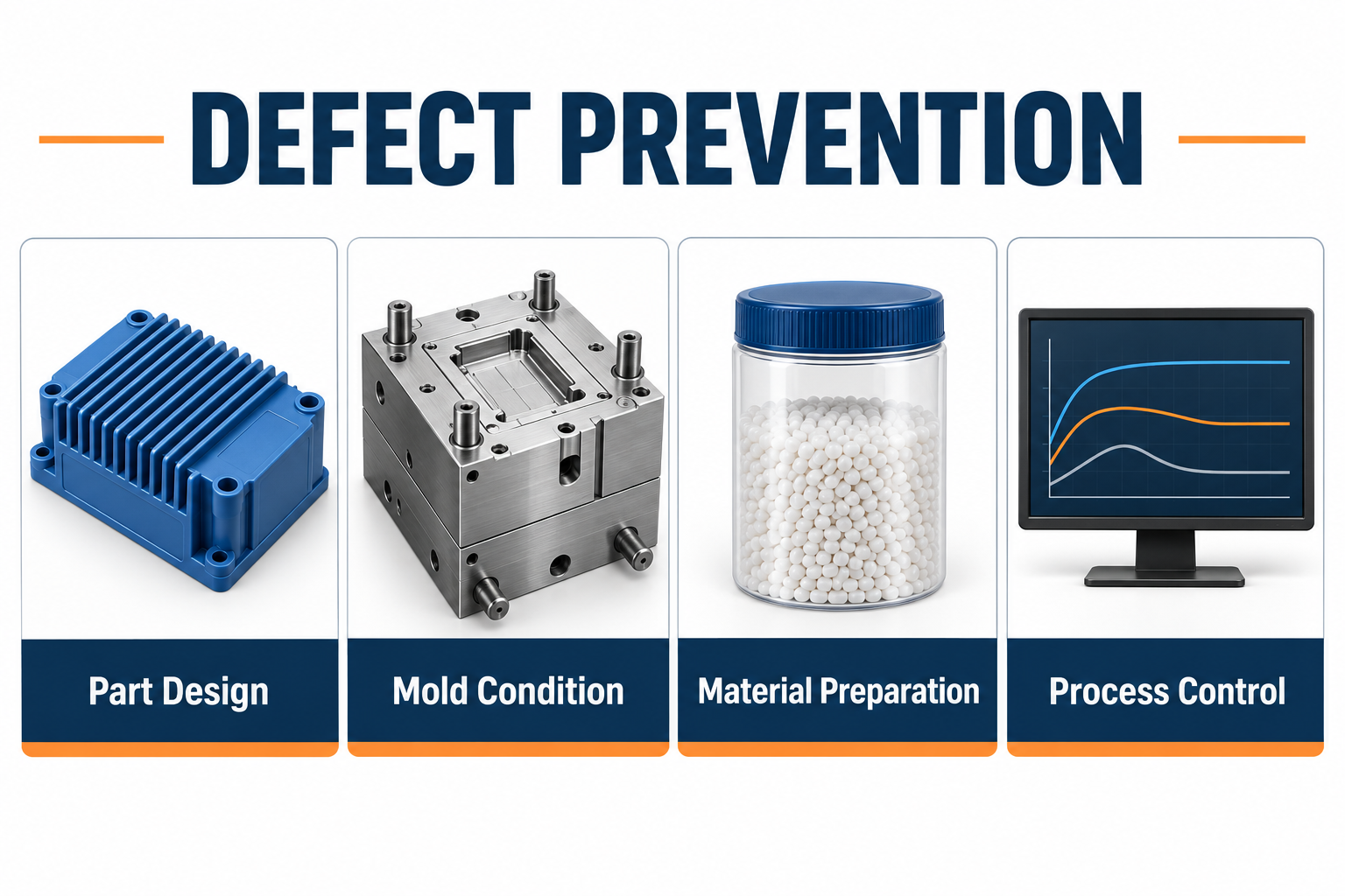
形 2. Prevention connects design, ツーリング, material preparation, およびプロセス制御. Icons are conceptual.
How Do You Prevent Material-Related Defects?
Control resin identity, 水分, 汚染, and thermal exposure according to the actual grade’s requirements.
Check the material label against the approved specification. Record the lot, 着色料, 添加物, and permitted regrind content.
Verify Drying Rather Than Only Dryer Settings
For grades requiring drying, follow the supplier’s temperature, 時間, 気流, and moisture recommendations. Verify the relevant equipment performance and material condition.
A displayed dryer temperature does not establish that the resin reached its moisture target. Consider hopper residence, スループット, transfer exposure, and measuring method.
Moisture can create streaking. In hydrolysis-sensitive polymers, it can also reduce molecular weight during processing. The severity and mechanism depend on the polymer.
Do not assume every silver streak indicates wet resin. Air, volatile contamination, and degradation can produce similar symptoms. Covestro’s molding-defect guide distinguishes visually similar streak mechanisms.
Control Changes And Contamination
Keep material transfers and containers identified. Review cleaning after resin or color changes, including conveying equipment and the plasticizing system.
Investigate whether black specks appear after a stoppage or changeover. That pattern may point toward retained or degraded material.
Do not approve an unreviewed resin substitution merely because the part still fills. 寸法, 強さ, 仕上げる, and process stability may change.
How Does Mold Condition Affect Defect Prevention?
Maintain venting, 冷却, shutoffs, and ejection so the tool performs as intended throughout production.
Inspect vents for deposits and blockage. Vent dimensions must suit the resin and tool design; excessive depth can create flash.
Check cooling circuits for flow restrictions, 漏れ, and temperature imbalance. The controller setting alone does not reveal local cavity conditions.
Inspect parting surfaces, インサート, スライド, and ejector clearances where flash or damage repeatedly occurs. Map defects by cavity to identify localized problems.
Do not compensate for damaged shutoffs by increasing clamp force indefinitely. A tool defect requires an appropriate tool correction and subsequent verification.
Record maintenance findings and changes. If a defect begins after repair, compare the affected features and cooling or venting conditions.
How Should You Troubleshoot Each Defect?
Choose corrections from a confirmed mechanism, then check for side effects on the complete part.
Keep process changes within the resin and equipment limits. The following diagnostic paths guide investigation rather than prescribe universal settings.
ショートショット
First confirm shot delivery, fill time, pressure behavior, and the transfer from filling to packing. Check whether the problem is repeatable or intermittent.
For repeatable incomplete regions, inspect the flow path and venting. For changing shot sizes, investigate delivery consistency before modifying the cavity.
Autodesk recommends reviewing the cause before selecting a short-shot remedy. それを参照してください short-shot guidance.
フラッシュ
Locate the exact escape path. Determine whether the flash appears during filling or develops during packing.
Review tool closure and shutoff condition before increasing clamp force. If excessive cavity pressure is involved, evaluate the filling and packing transition.
Reducing pressure until flash disappears is insufficient if the part becomes underpacked or dimensionally incorrect.
Sink Marks And Voids
Check whether the affected region contains a thick mass or receives limited packing. Evaluate the gate and local cooling conditions.
従来のフリーズオフ ゲートの場合, additional holding after gate seal cannot add material through that gate. Confirm the useful packing interval.
An internal cavity may be a shrinkage void or gas-related bubble. Sectioning or suitable nondestructive inspection may help distinguish them.
Do not assume better surface appearance proves internal soundness. Verify the relevant strength, 密度, or internal feature requirements.
反り
Measure the part under defined temperature, コンディショニング, and support conditions. A fixture can conceal free-state distortion.
Compare cooling balance, packing distribution, and material orientation. 強化樹脂用, flow direction can affect shrinkage behavior.
Inspect ejection and handling if deformation develops during release. Longer cooling alone may not correct an orientation-driven problem.
ウェルドライン
Locate the line relative to holes, ゲート, and applied loads. A meeting front is not automatically an open crack.
Evaluate venting and the material condition where fronts join. Trial temperature or speed changes only within a justified process investigation.
Celanese’s EVA molding guide emphasizes placing meeting fronts away from highly stressed regions. Its processing advice is material-specific.
Improved appearance does not establish restored strength. Test the relevant load or sealing function on representative samples.
Burn Marks And Discoloration
End-of-fill scorching can indicate trapped compressed gas. Inspect the vent path and local filling sequence.
Random dark streaks or specks may require a different investigation into contamination or thermal degradation. Record whether they follow downtime or material changes.
Increasing clamp force is not a general remedy for burning. It can reduce available venting at the parting surface.
Jetting And Flow Marks
Jetting can occur when a narrow melt stream enters open space without establishing normal wall contact. Inspect the gate geometry and entry direction.
Autodesk’s jetting explanation links the defect to restrictive passages and high entry velocity.
A staged filling profile may help in suitable cases. Simply increasing speed can worsen jetting even when faster filling helps another defect.
Ejection Marks And Cracking
Compare samples before and after handling where practical. Determine whether whitening or distortion appears during release.
Check draft, こだわり, 冷却, ejector support, およびアライメント. Reduce localized release stress rather than relying on repeated cosmetic rework.
What Is A Reliable Troubleshooting Workflow?
Record a baseline, test a specific hypothesis, and verify the correction over a representative stable run.
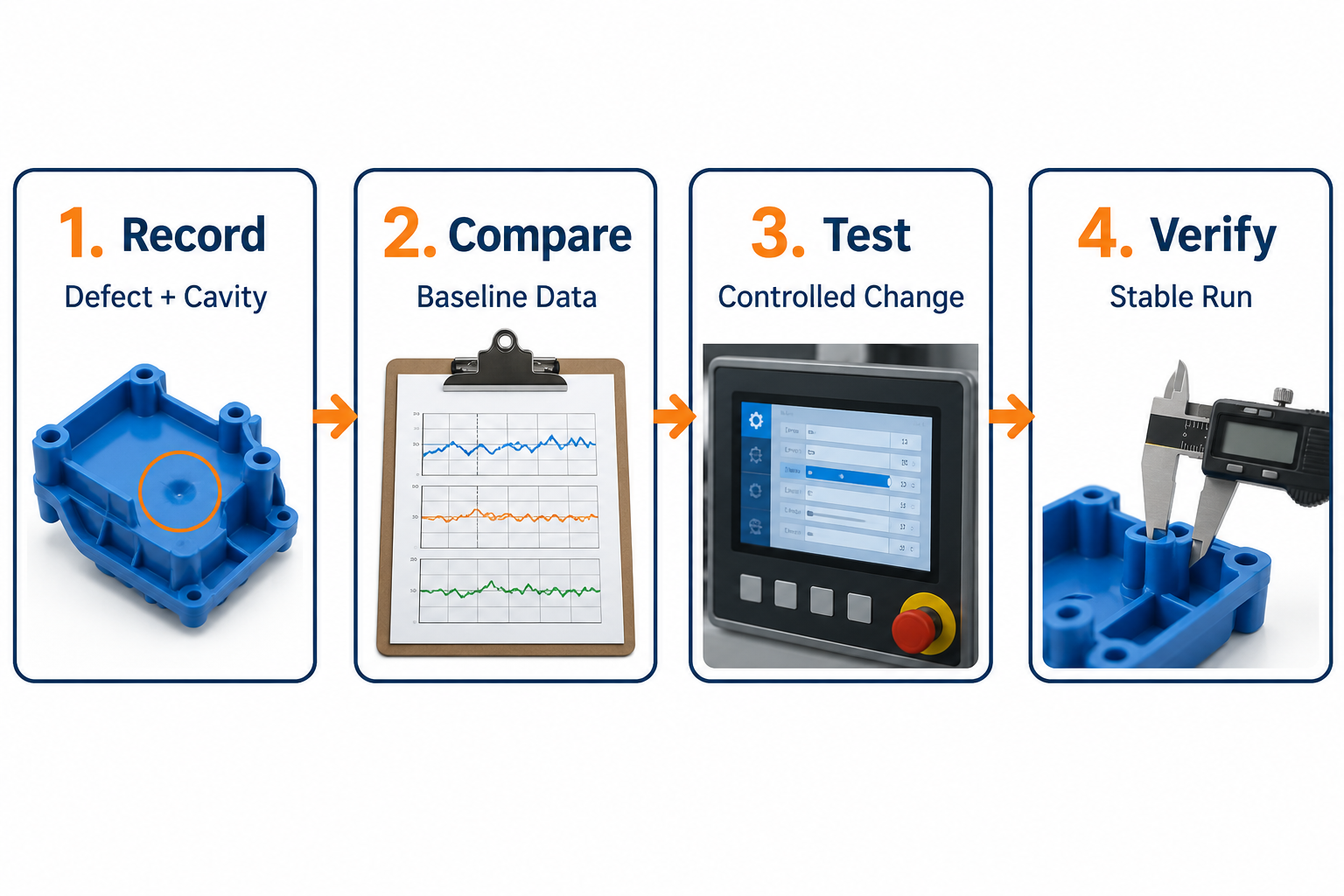
形 3. Record, 比較する, テスト, and verify. Illustrative data and instruments, not a measurement procedure.
Record The Evidence
Retain acceptable and defective samples. Record cavity, 時間, resin lot, material preparation, actual process data, and recent changes.
Measure the defect rate against a defined acceptance rule. Photographs need scale and consistent lighting when they support appearance decisions.
Compare Against A Known Baseline
Check actual values rather than only setpoints. Include fill time, pressure response, cushion, recovery behavior, and relevant temperatures.
A defect isolated to one cavity suggests a different investigation from a change affecting every cavity. Treat that pattern as evidence, not proof.
Test A Controlled Change
Change one factor at a time for a simple diagnostic test. Where interactions matter, use a planned experiment rather than uncontrolled simultaneous adjustments.
Allow the process to stabilize and identify samples from each condition. Record both the intended improvement and any new defect.
Verify And Standardize
Confirm appearance, 重要な寸法, および機能. Include all affected cavities and relevant startup or restart conditions in the validation plan.
Update approved settings, maintenance actions, and inspection instructions after approval. Establish a reaction plan if the defect returns.
What Should Buyers Specify Before Production?
Define acceptance requirements before tooling approval so your supplier can design the process and inspection around them.
| 要件 | 同意する情報 |
| 外観 | Visible zones, 点灯, viewing method, and limit samples |
| 寸法 | Critical features, datums, コンディショニング, and measurement method |
| 関数 | 組み立て, 負荷, leak, or cycle testing where applicable |
| 材料 | Exact grade, 色, 添加物, regrind policy, and records |
| サンプリング | 空洞, 量, トレーサビリティ, and approval responsibilities |
| Change control | Review required after tooling, 樹脂, or process changes |
Avoid accepting a sample solely because its surface looks clean. Hidden voids, degraded material, and residual stress may require additional evaluation.
TOPS一覧 プラスチック射出成形サービス. Confirm project-specific tooling, 材料, and inspection scope during review.
Request A Molded-Part Review with CAD, 図面, 樹脂グレード, defect photos, 重要な要件, 年間生産量, そしてプログラムライフ.
よくある質問
These answers help separate defect symptoms from the evidence needed to select a correction.
Can You Eliminate Every Injection Molding Defect?
You can reduce defect risk and control production against defined requirements. No general process setting guarantees defect-free output across all geometries and materials.
Does Increasing Injection Pressure Fix Short Shots?
Only when insufficient available pressure contributes to the problem. Blocked vents, inconsistent delivery, or unsuitable geometry may require different corrections.
Are Silver Streaks Always Caused By Moisture?
いいえ. Moisture is one possible cause. Investigate entrained air, 汚染物質, volatiles, and thermal history before deciding on drying alone.
Can More Clamp Force Stop Burn Marks?
It is not a general solution. Trapped gas requires an effective escape path. Excessive clamping can reduce venting and aggravate the problem.
Are All Weld Lines Weak?
Their effect depends on resin, 向き, 幾何学, and meeting conditions. Evaluate the relevant function rather than classifying strength from visibility alone.
Can Inspection Prevent Defects?
Inspection detects nonconformance. Prevention requires controlling the causes. Use inspection results to maintain the process and verify corrective actions.
結論
Prevent injection molding defects by linking part design, material preparation, mold condition, and process evidence. Diagnose the mechanism before changing settings. Verify the entire part after each correction, then document the approved process. Clear acceptance criteria make both supplier review and production control more reliable.


