Application first
Tell us whether your part is a visual model, tooling pattern, protective insert or checking aid. Its purpose guides material and process selection.


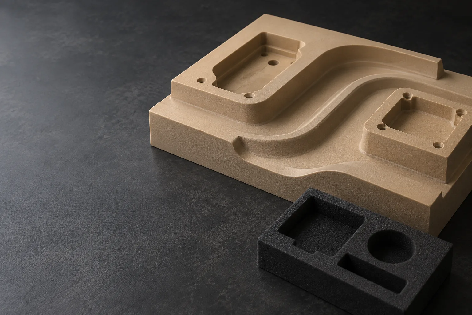
CUSTOM FOAM PARTS · TOPS PRECISION
Custom foam prototypes, tooling models and engineered inserts, made from your drawings.
TOPS Precision provides CNC foam milling project support from Dongguan, 中国. Send your CAD files, foam grade and application for a review of material suitability, ツールアクセス, dimensional requirements and the right manufacturing route.
Choose the material before the tolerance.
リジッドPUツーリングボード, compressible EVA or PE, and lightweight EPS or XPS behave differently during machining and inspection. 材質グレード, density and the function of the part determine what can be quoted. Flexible foam requests are reviewed for milling versus knife, die or other suitable cutting methods.
A DRAWING-LED APPROACH
Define the requirements that matter before committing to a manufacturing process.
Tell us whether your part is a visual model, tooling pattern, protective insert or checking aid. Its purpose guides material and process selection.
Review critical features, cutter access, deep pockets and workholding before the machining plan is agreed.
Confirm reference surfaces and measurement conditions. A soft insert needs different acceptance criteria from a rigid tooling board.
Confirm material, 量, 仕上げ, inspection deliverables, packaging and delivery requirements in the quotation.
FROM CAD TO CUSTOM GEOMETRY
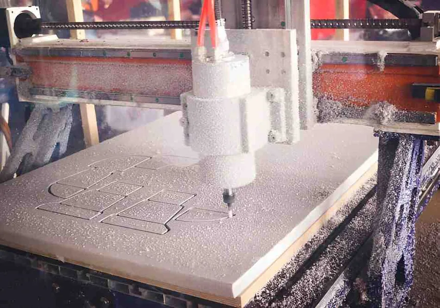
CNC milling removes material with a rotating cutter to create controlled pockets, profiles and contoured surfaces. The machining plan depends on the selected foam and geometry.
Tool-accessible 2D outlines, recessed pockets, チャンネル, holes and stepped surfaces can be assessed from your drawing. Internal corners retain a radius related to the cutter.
Contoured forms and master-pattern geometries can be evaluated from solid CAD or a suitable mesh. アンダーカット, tall features and multi-sided parts require a setup review.
Specify cavity fit, compression allowance and handling requirements. For flexible foam, the review determines whether milling or a different cutting process is more practical.
Additional-axis machining: availability and benefit are confirmed for the individual project; no universal multi-axis foam capability is implied.
GRADE & DENSITY MATTER
The following are material families to discuss, rather than a stock list or a guarantee that every grade can be milled. Send the supplier datasheet where available.
| 材料ファミリー | 一般的な使用方法 | What to confirm |
|---|---|---|
| Rigid polyurethane tooling board | Master patterns, form models, checking aids | Exact grade, 密度, edge stability, temperature and coating compatibility |
| EVA foam | Equipment inserts and cushioning pads | Compressibility, cell structure, pocket fit and milling versus cutting suitability |
| ポリエチレン (PE) フォーム | Transit protection and case interiors | 学年, 密度, layered construction and recovery after compression |
| Expanded polystyrene (EPS) | Lightweight models, forms and patterns | Bead size, local edge breakout, handling strength and finish expectations |
| Extruded polystyrene (XPS) | Prototype forms and model contours | 学年, stock thickness, surface damage and compatibility with adhesives or coatings |
| PVC / structural foam | Specialized models and composite-core geometry | Product construction, structural requirements and machining feasibility |
| ネオプレン / EPDM and other flexible foams | Pads, seals and gasket-type profiles | Application-specific process review; 2D cutting may be more suitable than milling |
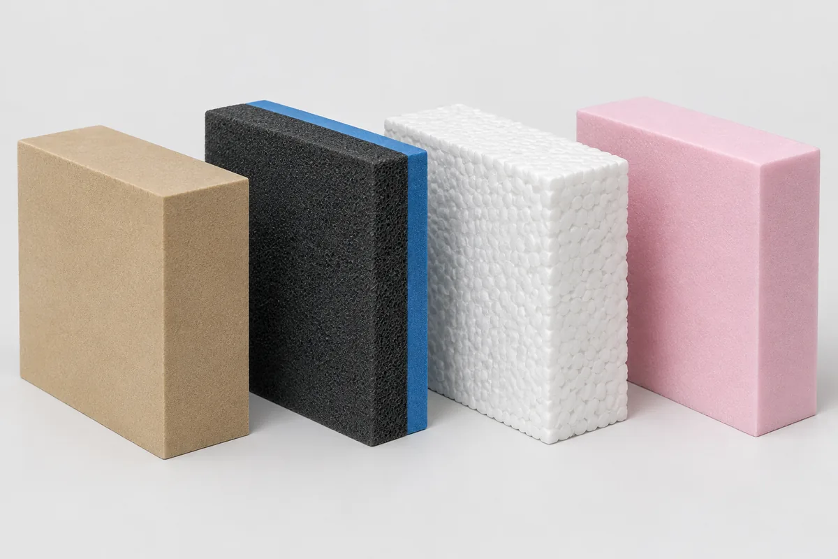
PU is a material family, not a single stiffness or density. A rigid model board can retain detailed geometry; a soft cushioning grade deforms under a clamp or measuring probe. Specify the actual product grade rather than requesting “PU foam” alone.
Material reference: Sika’s polyurethane model-board guidance describes machinability and model applications for a specific grade. It is a technical reference, not a statement of TOPS stock or brand affiliation.
GEOMETRY WITH A PURPOSE
Use these component types to describe your enquiry. Material and manufacturing feasibility are confirmed against your files.

Rigid tooling board · contoured geometry · prototype or pattern evaluation.

Flexible foam · shaped cavities · instrument storage and transit protection.

Lightweight model foam · freeform surfaces · form, space and assembly studies.
Other enquiries include custom profiles, layered supports, packaging forms and checking aids. Functional suitability is evaluated separately from the ability to machine a shape.
AGREE THE ACCEPTANCE CRITERIA
| 仕様 | How it is defined for your project |
|---|---|
| プロセス | CNC milling or routing for suitable grades and tool-accessible features; flexible foam may need an alternative cutting route. |
| Workpiece size | Provide overall length × width × height in mm. Machine envelope, fixturing allowance and stock availability are confirmed in the quotation. |
| Rigid-foam tolerance | Reviewed by grade, 密度, feature geometry and inspection method. No blanket ±0.05 mm tolerance applies to all foam parts. |
| Flexible-foam tolerance | Define the unloaded or specified compressed condition, サポート, measurement force and functional fit criteria. |
| Minimum feature / 壁 | Depends on foam strength, カッター径, wall height and unsupported length. Drawing review is required. |
| 仕上げる | As-machined condition specified first; サンディング, sealing or coating assessed separately for suitability and availability. |
| Order quantity | Prototype and low-volume enquiries; repeat or higher-volume work subject to process and cost review. |
| ファイル | ステップ / STP or IGES / IGS for solids, STL for suitable meshes, DXF for profiles, and PDF for dimensions and notes. |
| リードタイム | Quoted after material sourcing, サイズ, setups, 仕上げ, quantity and inspection requirements are reviewed. |
| 検査 & パッキング | Agreed critical dimensions, 表面状態, material identification and packaging to limit crushing or compression. |
A CLEAR PROJECT SEQUENCE
Identify dimensions, interfaces, tolerances and whether the part is a model, pattern or functional insert.
Agree the grade, stock dimensions and relevant supplier data before selecting tools or cutting methods.
Plan support and clamping without excessive compression, then select cutter reach, roughing and finishing paths.
Use parameters appropriate to the foam. Check tearing, local breakout, heat effects and remaining tool marks.
Check agreed features under the defined measurement conditions. Confirm fit or sample approval where required.
Protect edges and contoured surfaces, avoid crushing, and agree shipment details for the destination.
DESIGN FOR THE SELECTED FOAM
密度, stiffness and cell structure influence deflection and edge integrity. Density alone is not a tolerance specification: compare the grade’s properties and the part geometry before setting acceptance limits.
There is no universal minimum. 薄い, tall or unsupported walls can tear or distort during cutting, release and handling. Identify delicate features so their thickness and support can be reviewed.
Sharp suitable cutters, 制御された切断パラメータ, chip evacuation and planned finishing passes help manage the surface. Milling creates chips or dust; a clean finish without sanding cannot be guaranteed for every foam.
Provide radii that suit the cutter and avoid unnecessarily deep narrow cavities. Long tool reach, multiple setups or bonded sections may increase cost. Undercuts need a specific access review.
Use practical stock thickness, simplify tool access, group repeat parts and apply tight tolerances only to functional features. Compare machining with 2D cutting for flat flexible-foam parts.
SELECT THE RIGHT ROUTE
Choose milling when controlled 3D contours, stepped pockets or tool-accessible cavities justify the machining time.
| 方法 | Where it is useful | Main constraint |
|---|---|---|
| CNCフライス加工 / ルーティング | 3D forms, ポケット, contours and prototypes | Tool access, cutter radius, deformation and machining time |
| Hot wire cutting | Suitable EPS/XPS forms and swept profiles | Thermal compatibility and wire-accessible geometry |
| Waterjet cutting | Compatible foam-sheet profiles | Wetting, kerf, support and drying requirements |
| Die cutting | Repeat 2D pads, gaskets and inserts | Die cost and limited 3D geometry |
| Knife cutting | Flexible sheets and shaped outlines | Blade access, compression and limitations on deep contours |
This comparison explains process selection; availability of each method is confirmed during your project review.
INDUSTRIAL USES
Form studies, dimensional mock-ups and assembly trials. Explore CNC prototyping services.
Styling models, trim mock-ups and protective inserts. A model is not automatically qualified as an end-use automotive component.
Instrument storage, case interiors, organizers and transportation protection. Specify any antistatic or cleanliness requirements.
Master patterns, development forms and checking aids. 温度を確認する, chemical compatibility and loading for the intended process.
MEASUREMENT WITHOUT DISTORTION
Agree how the part will be accepted before production. Compressible foam can give different readings under different contact forces or support conditions.
ANSWERS FOR YOUR RFQ
CNC foam milling is a subtractive process that uses a rotating cutter and a programmed toolpath to remove material from a foam block. It can create profiles, pockets and 3D contours where the cutter can reach.
Suitable rigid PU tooling boards, EPS, XPS and other machinable grades can be evaluated. エヴァ, PE, neoprene and EPDM require a material-specific process review because flexible foam may be better suited to knife or die cutting.
Tolerance depends on the exact foam grade, 密度, 剛性, feature geometry and inspection conditions. TOPS confirms acceptance criteria during drawing review; a universal ±0.05 mm tolerance is not quoted for all foam parts.
Some grades and geometries may be suitable, but compression, tearing, workholding and cutter access must be evaluated. Submit the grade, density and required cavity fit so milling can be compared with other cutting methods.
Both remove material with a rotating cutter. Routing often describes machining on a router-style machine, particularly sheets or large foam forms. The relevant differences are the machine setup, toolpath, access and suitability for the selected material.
Send a STEP or IGES solid, or a suitable STL mesh, together with the critical dimensions. TOPS reviews contoured geometry, アンダーカット, tool reach, setups and material suitability before confirming the manufacturing scope.
Material grade and availability, blank size, 幾何学, setups, 仕上げ, 量, inspection and packaging all affect the quote. Deep narrow cavities and unnecessary tight tolerances can increase machining time.
Provide CAD and a dimensioned drawing, foam grade and density, quantity per part, 応用, overall dimensions, critical tolerances and inspection conditions, 仕上げる, 配送国と対象日.
SEND YOUR DRAWINGS
Include material grade and density, overall dimensions, quantity per part, 応用, critical requirements and delivery destination. TOPS will review feasibility and provide a project-specific quotation.