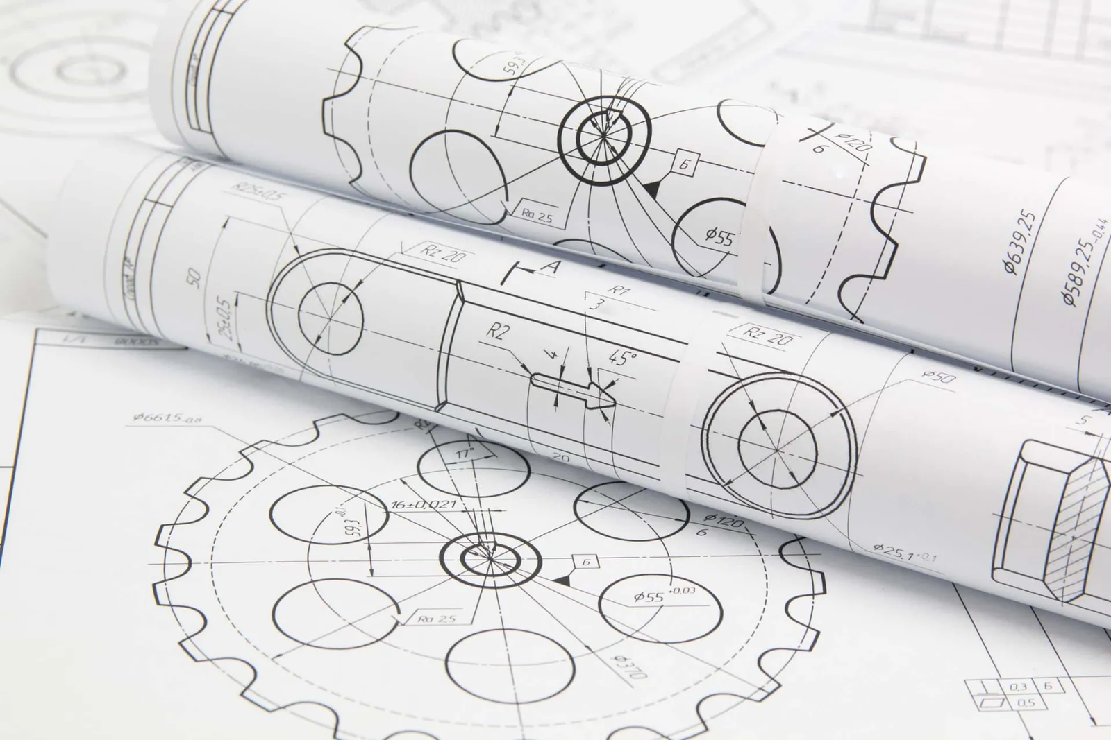
Техническите чертежи са критична част от производствения процес. Независимо дали произвеждате CNC обработени части, Компоненти на ламарина, продукти с инжектиране, или части от изкопаване -Добре подготвената техническа рисунка гарантира, че вашият дизайн може да бъде точно произведен.
В това ръководство, Ще разгледаме всичко, което инженерите трябва да знаят за подготовката на професионални технически чертежи за производство, включително стандарти за рисуване, ключови елементи, CAD софтуерни съвети, и специфични изисквания за рисуване за различни производствени процеси.
Защо техническите чертежи са толкова важни в производството?
Помислете за техническа рисунка като подробно ръководство за инструкции за изработка на вашия продукт. Тя казва на фабриката:
Как изглежда частта от всеки ъгъл
Точният размер на всяка функция
Какви материали да използвате
Колко гладка или груба трябва да бъде повърхността
Колко стегнати или разхлабени определени части трябва да се поберат заедно
Без тези подробности, Фабриката трябва да гадае - и предположението може да доведе до грешки, закъснения, или допълнителни разходи.
Техническите рисунки помагат да се избегнат скъпи грешки
Производството е свързано с прецизността. Дори малка грешка по размер или форма може да причини големи проблеми - особено за части, използвани в машините, автомобили, или електроника. Техническите чертежи Уверете се, че всички - от инженера до оператора на машината - са на една и съща страница.
Техническите рисунки са универсален език
Друга причина, поради която рисунките имат значение, е, че те използват стандартни символи и правила, които хората във фабриките по света разбират. Дали вашите части се правят в Китай, Германия, или САЩ, Правилното техническо рисуване помага да се избегне неправилно общуване.
Техническите чертежи помагат за управление на качеството
Накрая, Техническите рисунки задават стандартите за качество на вашия продукт. Те казват на производителя точно това, което очаквате - и ви дават нещо, срещу което да пристигнат кога пристигат готовите части.
Накратко, Ако искате вашият продукт да бъде направен правилно първия път - навреме и на бюджет - никога не пропускайте техническата рисунка!
Международни стандарти за технически чертежи
Техническите стандарти за рисуване са като „правилата на играта“. Те се уверяват, че независимо къде се правят вашите части - в Китай, Европа, или Америка - всеки разбира едни и същи символи, измервания, и насоки.
Без тези стандарти, Всяка компания може да рисува нещата по различен начин, което води до объркване, грешки, или забавяне на производството.
Двата най -често срещани стандарта, които трябва да знаете
Има две основни системи, използвани по целия свят за технически рисунки:
ISO стандарти (Международна организация за стандартизация)
Използва се главно в Европа, Азия, и много други части на света.
Фокусира се върху метричните единици (милиметри, сантиметри).
Включва указания за типове линии, символи, оразмеряване, допустими отклонения, и още.
Общи стандарти:
ISO 2768 (Общи допустими отклонения)
ISO 1302 (Повърхностна текстура)
ASME стандарти (Американско дружество на механичните инженери)
Използва се най -вече в Съединените щати.
Фокусира се върху имперските единици (инча) но също така поддържа метриката.
Добре известен стандарт: ASME Y14.5-Това е ръководството за геометрично оразмеряване и толерантност (GD&Т), което помага да се контролира формата, размер, и позиция на характеристиките в част.
Защо стандартите са толкова важни?
Представете си, че изпращате рисунката си във фабрика в чужбина - ако не използвате стандартен формат, Инженерите може да не разбират вашите символи или инструкции. Това може да доведе до:
Грешни размери на части
Лоши повърхностни завършвания
Неправилни разположения на дупки
Неуспешни проверки за качество
Но когато следвате ISO или ASME стандарти, Всички говорят един и същ „Технически език за рисуване“. Това прави процеса на производство по -бърз, по -лесно, и по -точно.
Съвет за инженери и дизайнери
Винаги проверявайте кой стандарт вашият производител предпочита, преди да изпраща вашите чертежи. например:
| Регион | Използван общ стандарт |
| Европа/Азия | ISO стандарт |
| САЩ/Канада | ASME стандарт |
Следвайки правилния стандарт показва професионализъм - и спестява време и пари както за вас, така и за вашата фабрика.
Ключови елементи на техническа рисунка
Техническата рисунка е нещо повече от скица - това е като подробен наръчник за инструкции за създаване на част. Всеки ред, Забележка, И символът има цел. Ако нещо липсва или е неясно, това може да доведе до грешки в производството или закъснения.
Нека разбием най -важните части, които трябва да има всяка добра техническа рисунка.
Заглавен блок
Това обикновено се намира в долния десен ъгъл на рисунката. Той предоставя основна информация като:
Име на част
Номер на част
Материал
Мащаб (Колко голяма или малка е рисунката с истинската част)
Дата на рисуване
Името на дизайнера или инженера
История на ревизията (показва дали рисунката е актуализирана)
Помислете за заглавния блок като личната карта на чертежа - тя помага на хората да знаят какво гледат.
Гледки към частта (2D или 3d)
Повечето рисунки показват различни гледни точки на част, за да се даде пълна картина. Общите изгледи включват:
Изглед отпред
Изглед отгоре
Страничен изглед
Изглед на секция (показва вътрешно изрязване)
Изометричен или 3D изглед (Незадължително, но полезно)
Множество изгледи помагат на фабриката да разбере формата, размер, и подробности за вашата част от всеки ъгъл.
Размери
Това е една от най -важните части на всяка техническа рисунка. Размерите казват фабриката точно колко голямо трябва да бъде всичко.
Типичните размери включват:
Дължина, ширина, височина
Размер и местоположение на дупките
Дебелина на стените
Радиус или диаметър на кривите
Винаги използвайте ясни и точни размери. Ако една фабрика трябва да се досети - това е лоша новина.
Допустими отклонения
Допустимите отклонения казват на производителя колко вариация е разрешена в размера на вашата страна.
например:
Размер на отвора от 10 мм ± 0,1 мм означава, че дупката може да бъде между 9,9 мм и 10,1 мм и все пак да е наред.
Допустимите отклонения са важни, защото нито един производствен процес не е перфектен - частите винаги имат малки вариации. Но колкото по -строг е толерантността, Колкото по -висока е цената.
Символи на повърхностното покритие
Тези символи показват колко гладка или груба трябва да бъде повърхността.
например:
Част, която се нуждае от полиране или обработка, ще има символ на повърхностно покритие със специфична стойност на грапавостта (като RA 3.2μm).
Без тези символи, Фабриката няма да знае дали повърхността трябва да е груба, гладко, или лъскаво.
Бележки и специални инструкции
Понякога, Ще трябва да добавите допълнителни бележки за неща, които не се вписват в другите категории. Това може да включва:
Материални изисквания
Инструкции за обработка на топлината
Повърхностно покритие (Като анодизиране или рисуване)
Инструкции за сглобяване
Изисквания за проверка на качеството
Добрата рисунка трябва да отговори на всеки въпрос, преди да бъде зададен.
Без предположение. Без предположения. Без грешки.
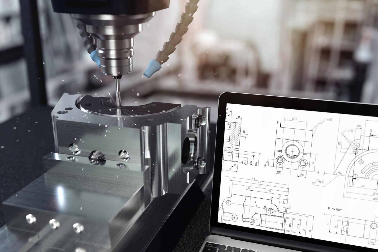
Подготовка на техническа рисунка с CAD софтуер
Ако сте нов в CAD, Може би се чудите - как всъщност да направя добра техническа рисунка?
Ето едно просто ръководство стъпка по стъпка, което да ви помогне да започнете.
стъпка 1: Започнете с 3D модел
Преди дори да започнете 2D рисунката си, Повечето инженери създават 3D модел на частта в техния CAD софтуер (като SolidWorks, Autocad, или сливане 360).
Този 3D модел ви дава:
Правилната форма на частта
Точни размери
Ясна идея за това как ще изглежда и се вписва
След като 3D моделът изглежда добре, Можете да генерирате вашите 2D технически чертежи директно от него. Това спестява много време в сравнение с рисуването от нулата.
стъпка 2: Добавете различни изгледи
След създаване на вашия 3D модел, Следващата стъпка е да поставите 2D изгледи във вашия лист за рисуване.
Общите изгледи включват:
Изглед отпред
Изглед отгоре
Страничен изглед
Изглед на секция (Ако е необходимо, за да се показват вътрешни подробности)
3D или изометричен изглед (Незадължително, Но полезно)
Изберете гледките, които най -добре показват важните характеристики на вашата страна.
стъпка 3: Добавете размери
След като вашите възгледи са на мястото си, Време е да добавите размери. Бъдете възможно най -ясни и подробни.
Не забравяйте да включите:
Общ размер (дължина, ширина, височина)
Позиции и размери на дупките
Дебелина на стената
Радиуси и ъгли
Критични измервания, които засягат функцията
Професионален съвет: Не добавяйте твърде много ненужни измерения - само това, което е необходимо за производството.
стъпка 4: Задайте допустими отклонения
След добавяне на размери, Трябва да определите допустимите отклонения-особено за важни или високоточни характеристики.
Има два начина за задаване на допустими отклонения:
Добавете специфични отклонения до измерение
Или, Задайте общи отклонения в заглавния блок (например: ± 0,1 мм, освен ако не е посочено друго)
Бъдете умни тук - тесните допустители означават по -високи разходи!
стъпка 5: Добавете изискванията за материал и повърхността
Следваща, Кажете на фабриката от какъв материал трябва да бъде направена част, и как повърхността трябва да изглежда или да се чувства.
Примери:
Материал: Алуминий 6061, Неръждаема стомана 304, ABS пластмаса
Повърхностно покритие: Обработена повърхност RA 3.2 μm
Покритие: Анодизиран, Боядисана, Полиран, и т.н.
Тази информация може да влезе в заглавния блок или като отделна бележка.
стъпка 6: Добавете бележки и специални инструкции
Понякога има подробности, които не се вписват в основната рисунка - като:
Топлинна обработка
Инструкции за сглобяване
Подробности за повърхностната обработка
Стандарти за проверка на качеството
Изисквания за опаковане
Добавете тези като ясни бележки на рисунката.
стъпка 7: Проверете всичко внимателно
Преди да изпратите рисунката си във фабриката, Проверете двойно всичко:
Са включени всички важни гледки?
Правилни ли са размерите?
Разумни ли са допустимите отклонения?
Посочен ли е материалът?
Изясни ли са всички специални инструкции?
Грешки в чертежа = закъснения, по -високи разходи, или лоши части.
Най -добрите технически рисунки са лесни за разбиране - дори за хората, които не говорят добре на вашия език.
Избягвайте ненужните подробности. Използвайте стандартни символи. И винаги мислете от гледна точка на фабриката.
Ясната рисунка спестява време, пари, И стрес за всички.
Специфични изисквания за различни производствени процеси
Различните методи на производство се нуждаят от различни видове информация за техническата ви рисунка.
Нека го разбием по прост начин.
Чертежи за обработка на ЦПУ - какво да включите
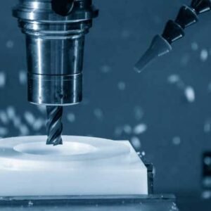
Обработката на ЦПУ използва инструменти за рязане за премахване на материал от блок метал или пластмаса.
Какви фабрики искат да видят във вашата рисунка:
Точни размери на всяка функция
Допустими отклонения за дупки, слотове, плоскост, и т.н.
Повърхностно покритие (например, Ra 3,2 μm)
Конци и потупани дупки (със стандартни обаждания)
Тип материал
Всякакви специални изисквания за обработка (като остри ръбове, Каца, или дебюриране)
Професионален съвет: Добавете само тесни допустими отклонения, когато това наистина има значение. Може да стане скъпо бързо!
Чертежи с ламарина - какво да включите
Частите от ламарина се правят чрез огъване, рязане, и пробиване на плоски метални листове.
Какво да покажете на вашата рисунка:
Изглед на плосък модел (преди огъване)
Огънете линии и посоки
Радиус на огъване и ъгли
Размери и позиции на отвора
Дебелина на материала
Повърхностна обработка (като прахово покритие или анодизиране)
Професионален съвет: Не забравяйте, че металът на огъване леко се разтяга или компресира материала - така че добавете бележка за надбавки за огъване, ако е необходимо.
Чертежи за инжекционно формоване - какво да включите
Инжекционното формоване е за пластмасови части, направени чрез инжектиране на разтопена пластмаса във форма.
Важни неща, които да се покажат:
Ъгли на чернова (обикновено 1 ° –3 °) За да помогнете за освобождаването на частта от формата
Дебелина на стената (Еднообразната дебелина е най -добра)
Ребра и поддържащи структури за сила
Места на щифта на портата и изхвърлянето (Ако е необходимо)
Тип материал (коремни мускули, настолен компютър, Найлон, и т.н.)
Повърхностно покритие (лъскав, матова, текстуриран)
Професионален съвет: Ако не сте сигурни в ъглите на черновата или дизайна на формата, Попитайте фабриката за съвет - те правят това всеки ден.
Рисунки за леене на матрици - какво да включвам
Умиращата се използва за изработка на метални части (като алуминий или цинк) със сложни форми.
Ключови подробности за добавяне:
Ъгли на чернова (Подобно на инжекционното формоване)
Дебелина на стената (избягвайте твърде дебели или твърде тънки)
Филета или радиуси, за да се избегнат остри ъгли
Тип материал (Алуминиев ADC12, Цинкова сплав, и т.н.)
Повърхностно покритие (As-cast, изстрел взривен, боядисана)
Всякакви обработващи зони след леене
Професионален съвет: Частите за леене на матрици често се нуждаят от допълнителна обработка за прецизни повърхности - покажете това ясно на вашата рисунка.
Всеки производствен процес има свои правила.
Преди да изпратите рисунката си, Запитайте се:
„Ако правех тази част с този процес, Какво ще трябва да знам?”
ясно, Простите рисунки помагат на фабриката да направи вашите части по -бързо, по-евтино, И с по -малко грешки.
Окончателни съвети за инженери
Техническите рисунки са основата на успешното производство. Добре подготвената рисунка гарантира, че вашите части са произведени правилно, бързо, и в рамките на бюджета.
Като следвате международните стандарти, Използване на правилни CAD техники, и персонализиране на чертежи за специфични производствени процеси, Инженерите могат да избегнат скъпи грешки и да доставят висококачествени продукти.
Вътрешно свързване:
Крайно ръководство за обработка на ЦПУ
Основно обяснение на инженерния чертеж
Инжекционно формоване срещу обработка на ЦПУ: Каква е разликата?
Разбиране на повърхностното довършване в производството
![]()