


Thin wall CNC machining needs controlled material removal, suitable support, and inspection under agreed conditions. You should define wall geometry, 素材の状態, and finished-part acceptance before ordering. A part measured while tightly clamped may behave differently after release.
Define Thin Walls By Their Geometry And Function
Your machining risk depends on wall height, unsupported length, floor area, and stiffness rather than thickness alone.
A short wall and a tall wall can share the same thickness but respond differently during cutting. Broad pocket floors create another challenge. Their flexibility can affect flatness, 厚さ, and assembly contact.
Identify which surfaces must seal, locate bearings, support electronics, or meet another component. Explain those functions during your design review. Avoid applying the tightest tolerance to every surface without a functional reason.
You should also distinguish machined walls from sheet metal or die-cast walls. Each route has different tooling, 幾何学, and production economics. This guide addresses parts cut from solid stock.
Separate Cutting Deflection From Released Distortion
You need to identify the cause of movement before choosing a corrective action.
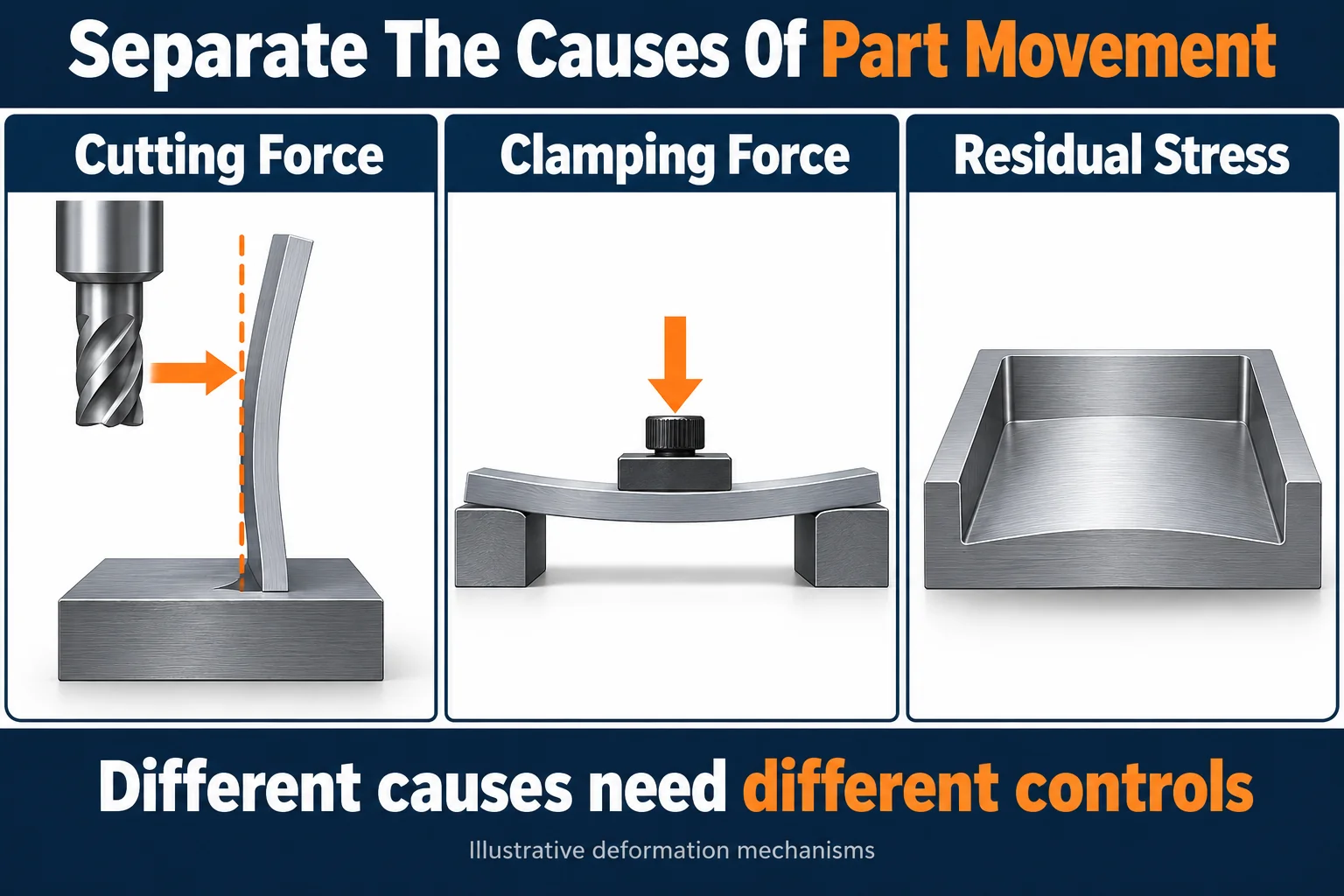
Cutting forces can temporarily deflect a flexible wall. Clamping can also deform the workpiece before machining begins. When forces disappear, the part can spring toward a different shape.
Residual stresses provide another mechanism. Removing material can change the internal stress balance and the released geometry. Temperature changes can further complicate comparisons between measurements.
The research paper Techniques For Thin Walled Element Milling examines post-machining deformation and contributing process factors. Its findings support reviewing several causes together, rather than assuming that every bowed part needs slower cutting.
For your project, request measurements at defined stages. Compare the clamped condition, released condition, and final inspection condition. Record the setup before changing the program.
Specify The Alloy Temper And Stock Form
Your material specification should identify the approved alloy, 気性, 製品形態, and traceability requirements.
Do not assume that two blanks bearing the same alloy number have identical machining behavior. Ask how the supplier selected the stock for your geometry. Require approval before substituting plate, 押し出し, or another product form.
Kaiser Aluminum’s plate product information identifies flatness and low distortion among selected product attributes. These attributes are product-specific. They do not guarantee that any machined thin wall will remain within your drawing limits.
If the supplier proposes intermediate thermal treatment, review its effect on the specified material condition. Approve the procedure and final property requirements before production. An informal instruction to heat the part is insufficient.
Preserve Support During The Machining Sequence
Your machining sequence should retain useful stiffness until the relevant surfaces are ready for finishing.
A supplier may rough the part while leaving planned finishing stock. It may then change setups or support before completing flexible sections. The suitable sequence depends on the pocket arrangement, 在庫状況, and available tool access.
Sandvik Coromant’s thin wall shoulder milling guidance varies the strategy with wall proportions. It describes staged machining and maintaining support beneath thinner sections. This is a useful engineering principle, not a universal cutting recipe.
Ask your supplier to explain which sections support the wall during each operation. Confirm how it handles broad floors and transitions near corners. Do not prescribe a fixed finishing allowance without checking the actual geometry.
| Design Feature | Manufacturing Concern | Decision Before Ordering |
|---|---|---|
| Tall Sidewall | Deflection and tool reach | Review height, access, and staged finishing |
| Broad Thin Floor | Axial loading and support | Agree on support and flatness inspection |
| Deep Narrow Pocket | Long tools and chip evacuation | Review corner radii and accessible tooling |
| Isolated Thin Rib | Loss of surrounding stiffness | Review sequence and retained support |
Review Fixtures And Cutting Forces Together
Your fixture should locate the part reliably without forcing flexible features into an artificial shape.
Clamps need suitable contact locations and support beneath the applied load. More force is not automatically better. Ask how the supplier confirms that tightening does not change the features being finished.
Sandvik Coromant’s milling vibration guidance recommends considering tool stability, force direction, and workpiece support. Those relationships explain why changing spindle speed alone may leave a fixture problem unresolved.
Consider whether sacrificial tabs, temporary support, or a dedicated fixture could improve the process. Treat these as options for review. Their suitability depends on access, 清潔さ, removal, and the final drawing.
For repeat orders, include fixture identification and setup instructions in the approved process. Record changes that could affect the released shape.
Agree On Inspection Before Machining Starts
You should define whether each critical characteristic is accepted free of restraint or under a specified assembly condition.
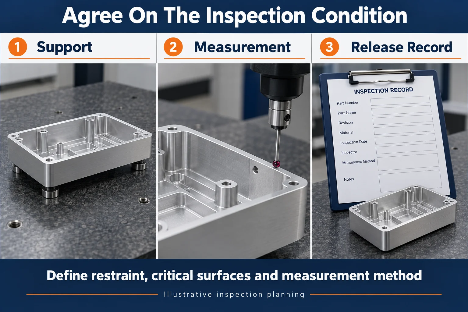
A fixture can help locate a part during measurement. It can also conceal movement if it pulls the part into shape. Your inspection plan should identify support positions, restraint, 向き, and any applied load.
Contact measurement can affect delicate features. Renishaw’s probe operation guidance discusses probing force and qualification practices. Ask your supplier how it establishes a suitable measurement method for your wall stiffness.
Specify the relevant surfaces and evaluation method for flatness or profile. Thickness measurements alone do not demonstrate flatness. 同じく, one indicator reading does not establish the shape of an entire surface.
Compare measurements after appropriate thermal stabilization. Record the conditions when temperature effects could matter. Ask for evidence that the chosen method can resolve the required acceptance limits.
| Inspection Item | Information To Agree |
|---|---|
| Part Condition | Free condition or defined restraint and load |
| 位置 | Support points, 向き, and datum setup |
| Critical Features | 壁の厚さ, floor flatness, profile, and mating surfaces |
| 方法 | 装置, probing approach, and evaluation procedure |
| Production Stage | After machining and after required finishing |
| Records | First article results, sampling plan, and change control |
Include Finishing And Handling In The Release Plan
Your final acceptance should reflect the part after all specified manufacturing operations.
バリ取り, 表面の準備, コーティング, and handling belong in the process review. Protect thin edges without rounding functional surfaces beyond their requirements. Specify cosmetic areas and packaging contact points where damage would affect assembly.
If the part requires anodizing, review our anodizing tolerance guide. Dimensional allowances for coating are separate from distortion control. Both need consideration when the finished part must fit another component.
Do not assume that a pre-finish inspection report proves final compliance. Identify which dimensions require verification after finishing and which process records support release.
Compare Quotes Against The Same Acceptance Scope
Your quotation comparison should include support, setup changes, 検査, and qualification rather than machining time alone.
Thin walls can require additional fixtures, staged operations, 慎重な取り扱い, or trial parts. A lower quote may reflect a different interpretation of the final inspection condition.
Send each bidder the same drawing revision, 材質仕様, 量, and acceptance criteria. Ask for exceptions before ordering. For a demanding new geometry, consider a first article before releasing the full production quantity.
TOPS Precision provides CNC加工サービス. Discuss the proposed wall geometry and inspection scope during project review. Confirm achievable requirements for your particular part rather than relying on a general minimum-wall claim.
よくある質問
Your final requirements should follow the part function and a reviewed manufacturing plan.
What Is The Minimum Wall Thickness For CNC Aluminum
There is no universal minimum for every geometry. Wall height, unsupported area, 合金, ツーリング, and acceptance criteria affect feasibility.
Does Slower Machining Prevent Warping
必ずしもではありません. You must distinguish cutting deflection from clamping deformation, residual stress effects, and thermal movement.
Should Thin Parts Be Inspected While Clamped
Only when the drawing specifies the relevant restraint condition. さもないと, agree on supports that do not conceal unacceptable deformation.
Can Ribs Or Larger Corner Radii Help
They may improve stiffness or tool access. Review their functional effects and machining implications before changing the design.
Is A Five Axis Machine Enough To Guarantee Accuracy
いいえ. Machine access helps, but material, ワークホールディング, process sequence, and measurement still need control.
Request A Thin Wall Machining Review
描いた絵を送ってください, alloy and temper, order quantity, critical surfaces, and inspection condition. 私たちのチームに連絡してください to review the geometry and production approach before requesting a quote.