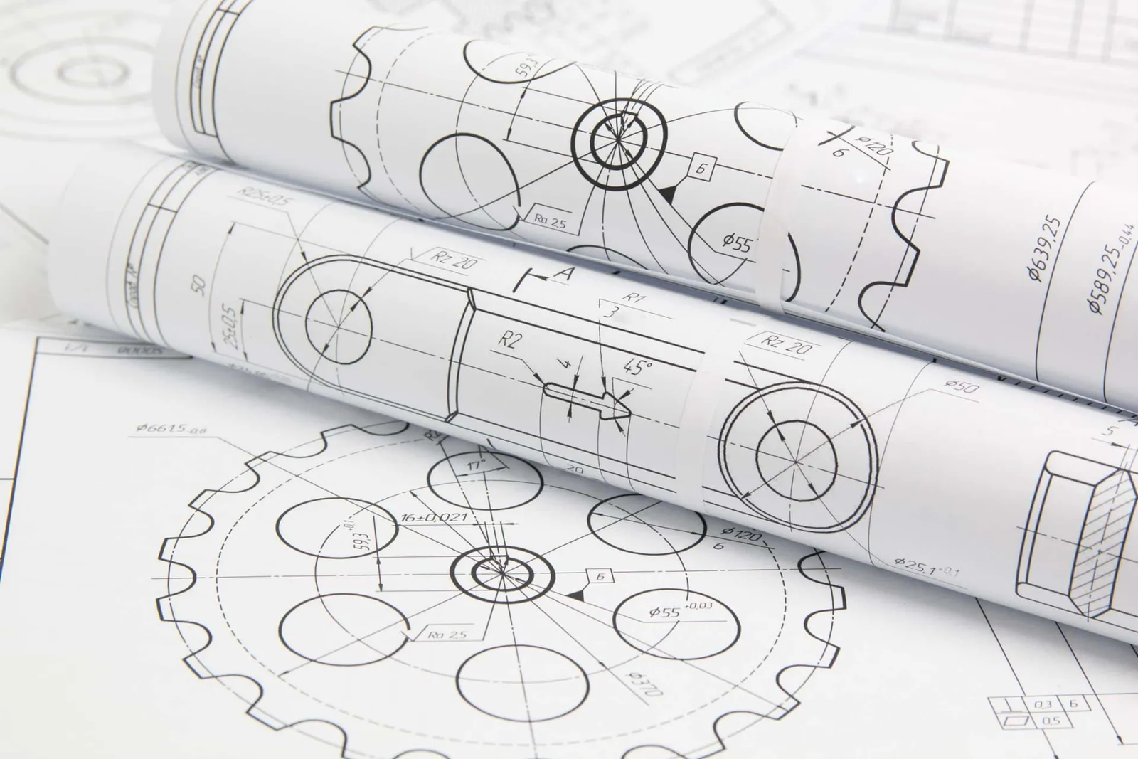
Technical drawings are a critical part of the manufacturing process. Whether you are producing CNC machined parts, sheet metal components, injection-molded products, or die-cast parts — a well-prepared technical drawing ensures your design can be accurately manufactured.
In this guide, we’ll cover everything engineers need to know about preparing professional technical drawings for manufacturing, including drawing standards, key elements, CAD software tips, and specific drawing requirements for different manufacturing processes.
Why Are Technical Drawings So Important in Manufacturing?
Think of a technical drawing like a detailed instruction manual for making your product. It tells the factory:
What the part looks like from every angle
The exact size of every feature
What materials to use
How smooth or rough the surface should be
How tight or loose certain parts need to fit together
Without these details, the factory has to guess — and guessing can lead to mistakes, delays, or extra costs.
Technical Drawings Help Avoid Costly Mistakes
Manufacturing is all about precision. Even a small error in size or shape can cause big problems — especially for parts used in machines, cars, or electronics. Technical drawings make sure everyone — from the engineer to the machine operator — is on the same page.
Technical Drawings Are a Universal Language
Another reason why drawings matter is that they use standard symbols and rules that people in factories around the world understand. Whether your parts are being made in China, Germany, or the USA, a proper technical drawing helps avoid miscommunication.
Technical Drawings Help Control Quality
Finally, technical drawings set the quality standards for your product. They tell the manufacturer exactly what you expect — and they give you something to check against when the finished parts arrive.
In short, if you want your product made right the first time — on time and on budget — never skip the technical drawing!
International Standards for Technical Drawings
Technical drawing standards are like the “rules of the game.” They make sure that no matter where your parts are made — in China, Europe, or America — everyone understands the same symbols, measurements, and guidelines.
Without these standards, every company might draw things differently, leading to confusion, mistakes, or delays in production.
The Two Most Common Standards You Should Know
There are two main systems used around the world for technical drawings:
ISO Standards (International Organization for Standardization)
Used mainly in Europe, Asia, and many other parts of the world.
Focuses on metric units (millimeters, centimeters).
Includes guidelines for line types, symbols, dimensioning, tolerances, and more.
Common standards:
ISO 2768 (General Tolerances)
ISO 1302 (Surface Texture)
ASME Standards (American Society of Mechanical Engineers)
Used mostly in the United States.
Focuses on imperial units (inches) but also supports metric.
Well-known standard: ASME Y14.5 — this is the go-to guide for Geometric Dimensioning and Tolerancing (GD&T), which helps control the shape, size, and position of features on a part.
Why Are Standards So Important?
Imagine sending your drawing to a factory overseas — if you’re not using a standard format, the engineers might not understand your symbols or instructions. This can lead to:
Wrong part sizes
Poor surface finishes
Incorrect hole placements
Failed quality checks
But when you follow ISO or ASME standards, everyone is speaking the same “technical drawing language.” It makes the manufacturing process faster, easier, and more accurate.
Tip for Engineers and Designers
Always check which standard your manufacturer prefers before sending your drawings. For example:
| Region | Common Standard Used |
| Europe/Asia | ISO Standard |
| USA/Canada | ASME Standard |
Following the right standard shows professionalism — and it saves time and money for both you and your factory.
Key Elements of a Technical Drawing
A technical drawing is more than just a sketch — it’s like a detailed instruction manual for making a part. Every line, note, and symbol has a purpose. If something is missing or unclear, it could lead to production mistakes or delays.
Let’s break down the most important parts that every good technical drawing should have.
Title Block
This is usually found in the bottom right corner of the drawing. It provides basic information like:
Part name
Part number
Material
Scale (how big or small the drawing is compared to the real part)
Drawing date
Designer’s or engineer’s name
Revision history (shows if the drawing has been updated)
Think of the title block like the ID card of the drawing — it helps people know what they’re looking at.
Views of the Part (2D or 3D)
Most drawings show different views of a part to give a complete picture. Common views include:
Front view
Top view
Side view
Section view (shows an inside cut)
Isometric or 3D view (optional but helpful)
Multiple views help the factory understand the shape, size, and details of your part from every angle.
Dimensions
This is one of the most important parts of any technical drawing. Dimensions tell the factory exactly how big everything should be.
Typical dimensions include:
Length, width, height
Hole size and location
Thickness of walls
Radius or diameter of curves
Always use clear and accurate dimensions. If a factory has to guess — that’s bad news.
Tolerances
Tolerances tell the manufacturer how much variation is allowed in your part’s size.
For example:
A hole size of 10mm ±0.1mm means the hole can be between 9.9mm and 10.1mm and still be OK.
Tolerances are important because no manufacturing process is perfect — parts always have small variations. But the tighter the tolerance, the higher the cost.
Surface Finish Symbols
These symbols show how smooth or rough a surface should be.
For example:
A part that needs polishing or machining will have a surface finish symbol with a specific roughness value (like Ra 3.2μm).
Without these symbols, the factory won’t know if a surface should be rough, smooth, or shiny.
Notes and Special Instructions
Sometimes, you’ll need to add extra notes for things that don’t fit into the other categories. This could include:
Material requirements
Heat treatment instructions
Surface coating (like anodizing or painting)
Assembly instructions
Quality inspection requirements
A good drawing should answer every question before it’s asked.
No guessing. No assumptions. No mistakes.
Preparing a Technical Drawing with CAD Software
If you’re new to CAD, you might be wondering — how do I actually make a good technical drawing?
Here’s a simple step-by-step guide to help you get started.
Step 1: Start with a 3D Model
Before you even begin your 2D drawing, most engineers create a 3D model of the part in their CAD software (like SolidWorks, AutoCAD, or Fusion 360).
This 3D model gives you:
The correct shape of the part
Exact dimensions
A clear idea of how it will look and fit
Once the 3D model looks good, you can generate your 2D technical drawings directly from it. This saves a ton of time compared to drawing from scratch.
Step 2: Add Different Views
After creating your 3D model, the next step is to insert 2D views into your drawing sheet.
Common views include:
Front view
Top view
Side view
Section view (if needed to show inside details)
3D or isometric view (optional, but helpful)
Choose the views that best show the important features of your part.
Step 3: Add Dimensions
Once your views are in place, it’s time to add dimensions. Be as clear and detailed as possible.
Remember to include:
Overall size (length, width, height)
Hole positions and sizes
Wall thickness
Radii and angles
Critical measurements that affect function
Pro Tip: Don’t add too many unnecessary dimensions — only what’s needed for production.
Step 4: Set Tolerances
After adding dimensions, you should define tolerances — especially for important or high-precision features.
There are two ways to set tolerances:
Add specific tolerances next to a dimension
Or, set general tolerances in the title block (for example: ±0.1mm unless otherwise specified)
Be smart here — tight tolerances mean higher costs!
Step 5: Add Material and Surface Requirements
Next, tell the factory what material the part should be made of, and how the surface should look or feel.
Examples:
Material: Aluminum 6061, Stainless Steel 304, ABS Plastic
Surface Finish: Machined surface Ra 3.2μm
Coating: Anodized, Painted, Polished, etc.
This information can go into the title block or as a separate note.
Step 6: Add Notes and Special Instructions
Sometimes there are details that don’t fit in the main drawing — like:
Heat treatment
Assembly instructions
Surface treatment details
Quality inspection standards
Packaging requirements
Add these as clear notes on the drawing.
Step 7: Check Everything Carefully
Before sending your drawing to the factory, double-check everything:
Are all the important views included?
Are the dimensions correct?
Are the tolerances reasonable?
Is the material specified?
Are all special instructions clear?
Mistakes in the drawing = Delays, higher costs, or bad parts.
The best technical drawings are easy to understand — even for people who don’t speak your language well.
Avoid unnecessary details. Use standard symbols. And always think from the factory’s point of view.
A clear drawing saves time, money, and stress for everyone.
Specific Requirements for Different Manufacturing Processes
Different manufacturing methods need different kinds of information on your technical drawing.
Let’s break it down in a simple way.
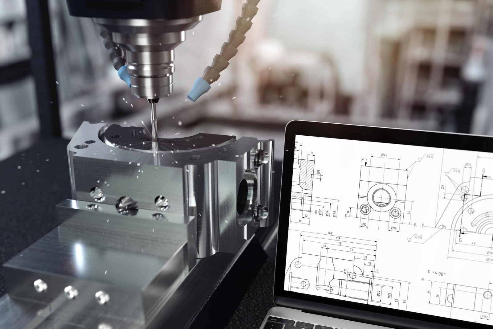
CNC Machining Drawings — What to Include
CNC machining uses cutting tools to remove material from a block of metal or plastic.
What factories want to see in your drawing:
Exact dimensions of every feature
Tolerances for holes, slots, flatness, etc.
Surface finish (for example, Ra 3.2μm)
Threads and tapped holes (with standard callouts)
Material type
Any special machining requirements (like sharp edges, chamfers, or deburring)
Pro Tip: Only add tight tolerances where it really matters. It can get expensive fast!
Sheet Metal Drawings — What to Include
Sheet metal parts are made by bending, cutting, and punching flat metal sheets.
What to show on your drawing:
Flat pattern view (before bending)
Bend lines and directions
Bend radius and angles
Hole sizes and positions
Material thickness
Surface treatment (like powder coating or anodizing)
Pro Tip: Remember that bending metal slightly stretches or compresses the material — so add a note about bend allowances if needed.
Injection Molding Drawings — What to Include
Injection molding is for plastic parts made by injecting molten plastic into a mold.
Important things to show:
Draft angles (usually 1°–3°) to help release the part from the mold
Wall thickness (uniform thickness is best)
Ribs and support structures for strength
Gate and ejector pin locations (if needed)
Material type (ABS, PC, Nylon, etc.)
Surface finish (glossy, matte, textured)
Pro Tip: If you’re not sure about draft angles or mold design, ask the factory for advice — they do this every day.
Die Casting Drawings — What to Include
Die casting is used for making metal parts (like aluminum or zinc) with complex shapes.
Key details to add:
Draft angles (similar to injection molding)
Wall thickness (avoid too thick or too thin)
Fillets or radii to avoid sharp corners
Material type (Aluminum ADC12, Zinc Alloy, etc.)
Surface finish (as-cast, shot blasted, painted)
Any machining areas after casting
Pro Tip: Die casting parts often need extra machining for precision surfaces — show this clearly in your drawing.
Every manufacturing process has its own rules.
Before you send your drawing, ask yourself:
“If I were making this part with this process, what would I need to know?”
Clear, simple drawings help the factory make your parts faster, cheaper, and with fewer mistakes.
Final Tips for Engineers
Technical drawings are the foundation of successful manufacturing. A well-prepared drawing ensures your parts are produced correctly, quickly, and within budget.
By following international standards, using proper CAD techniques, and customizing drawings for specific manufacturing processes, engineers can avoid costly mistakes and deliver high-quality products.
Internal Linking:
Ultimate Guide to CNC Machining
Engineering Drawing Basic Explained
Injection Molding vs CNC Machining: What’s the Difference?
Understanding Surface Finishing in Manufacturing
![]()