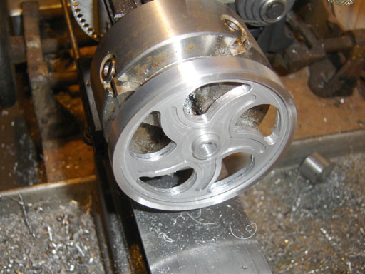
Comenzamos con tornos de servicio pesado para trabajos de gran diámetro
Los diámetros del volante suelen ser más que 500 milímetros. Nuestros centros de torneado pueden manejar este tamaño sin ningún problema.. Colocamos el tocho en un portabrocas de cuatro mordazas y lo sujetamos con fuerza., que detiene el movimiento durante pasadas de desbaste muy pesadas.
Al mecanizar, los diámetros grandes generan calor rápidamente. Ponemos mucho refrigerante en la zona de corte.. Esto mantiene las herramientas afiladas y los mismos tamaños..
Mantener el espesor de la pared uniforme durante todo el proceso de corte
El volante está desequilibrado porque las paredes no están niveladas.. Programamos pequeños pasos de cortes radiales. Cada pasada elimina la cantidad justa de material. Nuestras herramientas de torneado siempre avanzan al mismo ritmo..
El espesor final de la pared permanece igual en todo el borde., en 0.1 milímetros. Tomamos medidas en diferentes puntos durante el mecanizado.. Antes de pasar al siguiente paso, Comprobamos las dimensiones con calibradores digitales para asegurarnos de que todo sea igual..
Perforación de los asientos del cubo y del rodamiento para lograr un ajuste exacto
El diámetro del eje debe ser el mismo que el diámetro del cubo.. Utilizamos barras de mandrinar de carburo con insertos que se pueden cambiar.. Los asientos de los rodamientos necesitan cierto tipo de ajuste de interferencia.
Perforamos hasta dentro 0.01 mm del tamaño final. Una pasada de acabado con un inserto afilado le da la superficie que desea. El rodamiento se desliza fácilmente, sin ningún esfuerzo.
El sondeo en vivo detecta cualquier desviación antes de que se convierta en un problema
Nuestros tornos llevan integrados palpadores que miden durante el ciclo.. Después de cortes preliminares, la sonda comprueba los diámetros. El programa se modifica si algo se desvía. Esta retroalimentación en tiempo real evita que las piezas sean desechadas..
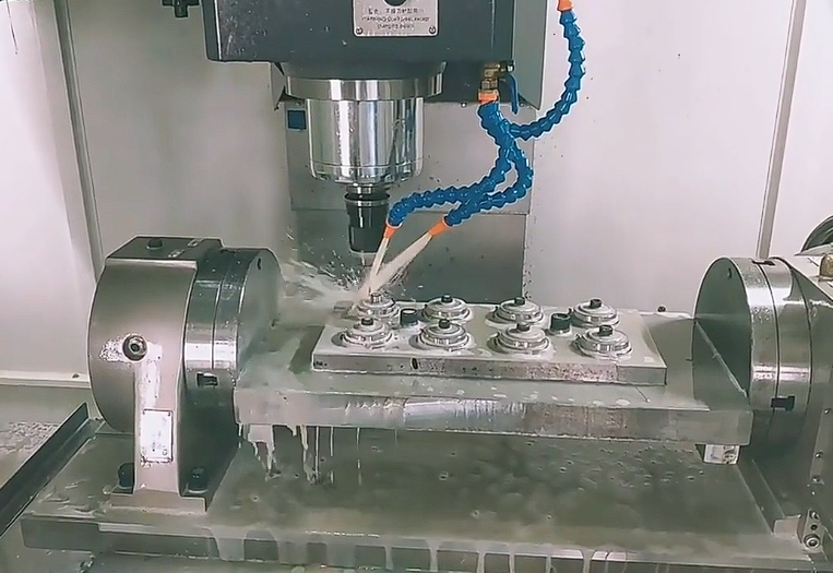
Nuestras fresadoras CNC crean características de volante de inercia y orificios de montaje de precisión
Cajas lacas, agujeros de montaje, y los bolsillos para reducir el peso deben estar en el lugar correcto. Usamos software CAM para planificar trayectorias de herramientas y características de la máquina que funcionarán de la misma manera en cada lote de volantes..
Patrones de perforación de pernos mientras el volante permanece indexado
Para montaje, los agujeros de los pernos deben estar perfectamente alineados. Ponemos el volante sobre una mesa que gira.. La mesa puede moverse en los ángulos correctos para cada hoyo.. Nuestras fresadoras CNC pueden perforar completamente en una sola pasada.
Utilizamos perforación profunda para deshacernos de las virutas que se quedan atrapadas en agujeros profundos.. Esto evita que los agujeros se rompan y mantiene su calidad.. No hay rebabas ni suciedad en ninguno de los agujeros..
Cortar chaveteros que coincidan con las dimensiones de su eje
Los chaveteros mueven el torque desde el eje al volante. Cortamos chaveteros utilizando fresas de extremo del tamaño adecuado para su chaveta de eje.. El molino desciende hasta el fondo y luego se mueve a lo largo del orificio..
Usamos calibres pasa/no pasa para medir el ancho del chavetero.. This proves that the key won't get stuck or rattle. The connection stays strong even when it's under stress.
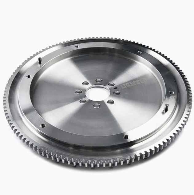
Quitar peso sin debilitar la estructura
Algunos usos necesitan volantes que sean más livianos pero aún fuertes.. Cortamos bolsillos en la red o el borde.. Usando FEA, Nuestros ingenieros determinan el tamaño que deben tener los bolsillos.. The flywheel stays strong and doesn't break.
Usamos fresas de punta esférica para hacer bolsillos.. El radio en la parte inferior evita que se formen grietas.. El volante puede soportar altas RPM sin romperse.
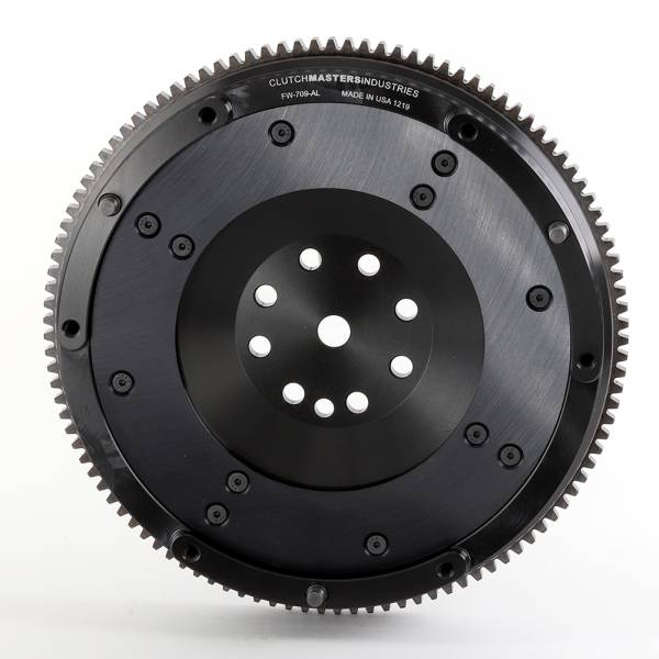
Agregar chaflanes para evitar que comiencen las grietas
La tensión se acumula en los bordes afilados, que puede provocar grietas. Redondeamos todos los cantos por fuera y por dentro.. Esto hace que el estrés cubra un área más grande.. Los chaflanes también hacen que sea más seguro manipular las piezas durante el montaje..