
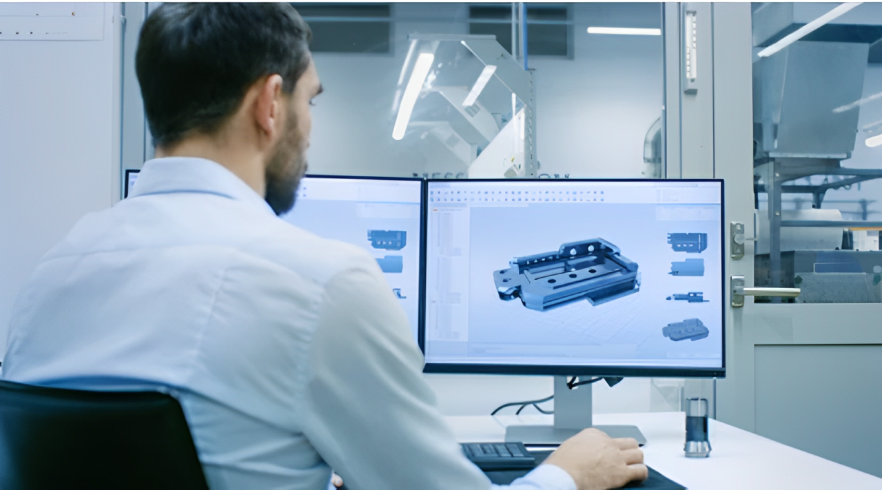
Usinage CNC, Un processus de fabrication avancé où la précision de la fabrication des composants dépend du dessin technique. Les machines CNC, comme des dessins d'usinage, Les plans pour vos pièces sont-ils coupés, percé, et en forme de matières premières. Ingénieurs, machinistes, et les fabricants doivent comprendre ces dessins techniques pour produire des composants en fonction des spécifications de conception.
Ce guide expliquera les dessins de la machine, Leur structure, Et leur importance. mis-à-part, Il vous dira comment les préparer à la meilleure performance d'usinage CNC.
Que sont les dessins d'usinage CNC?
Les dessins d'usinage CNC sont des représentations détaillées 2D ou 3D d'un composant, qui sont cruciaux pour une fabrication précise. Ces dessins techniques définissent les dimensions, géométries, tolérances, spécifications matérielles, et les instructions d'usinage. Ils sont utilisés comme plans pour Fraisage CNC, tournant, forage, et affûtage Opérations pour s'assurer qu'un machiniste et des machines CNC produisent des pièces précises et cohérentes.
Dessin d'usinage CNC, Une méthode de communication universelle entre les ingénieurs, designers, machinistes, et des équipes de qualité dans la fabrication moderne. Les dessins d'usinage contiennent des détails supplémentaires tels que les tolérances, ajustement, trous appel, finitions de surface, et d'autres détails de fabrication. Ces détails complètent la forme de la pièce telle que lorsqu'elle est usinée, La partie finale répond aux exigences fonctionnelles.
L'importance de l'usinage des dessins
Donc, Les paramètres suivants nous aideront à comprendre l'importance du dessin d'usinage:
1. Précision & Précision
Les dessins d'usinage donnent des dimensions de partie, tolérances, et les finitions de surface exactement spécifiées pour qu'il n'y ait pas d'ambiguïté. Cela signifie que chaque composant fabriqué sera conformément à la conception, avec des erreurs et une incohérence minimes.
2. Standardisation
Il permet aux machinistes et ingénieurs du monde, DEPUIS, et jis. Les dessins techniques sont standardisés afin que tout le fabricant, fournisseur, et les inspecteurs de qualité ont la même compréhension de l'intention de conception sans interprétation erronée.
3. Efficacité & Réduction des coûts
Des dessins d'usinage précis aident:
- Minimiser les opérations inutiles pendant l'usinage et les chemins d'outils.
- La phase de réduction à grande échelle comprend la définition d'outils précis, dimensions, et les tolérances pour prévenir le gaspillage matériel.
- Cela réduit le temps de configuration et d'usinage et crée des cycles de production rapides.
4. Contrôle de qualité & Inspection
Les équipes d'assurance qualité utilisent des dessins techniques comme référence pour vérifier que la partie finale est conforme aux spécifications de conception. Ces dessins sont utilisés par les ingénieurs inspecter des pièces pour:
- Tolérances dimensionnelles
- Exigences de finition de surface
- Tolérances géométriques (DG&T)
Anatomie de base d'un dessin technique d'usinage CNC
Le dessin d'usinage CNC se compose de quelques éléments importants qui aident le machiniste à comprendre la fabrication de la pièce. Les différentes sections du dessin remplissent différentes fonctions pour atteindre la précision, efficacité, et cohérence de la production.
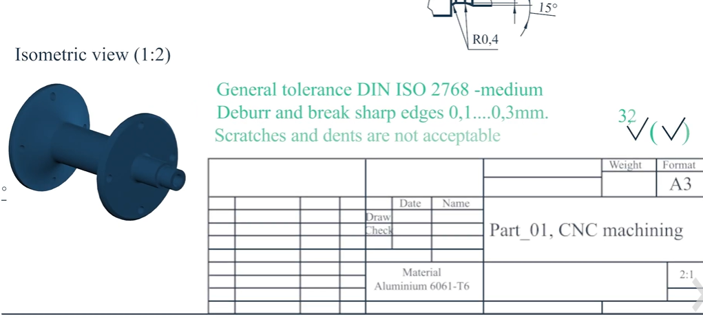
1. Bloc de titre
Presque tous les dessins d'usinage ont leur bloc de titre dans le coin inférieur droit. Il y aura des données cruciales telles que le nom de pièce, matériaux, échelle, nombres de dessin, et l'histoire de la révision. Dans cette section, ingénieurs, machinistes, et les inspecteurs de qualité peuvent trouver la version de dessin et le dessin sur lequel ils travaillent. Il peut également contenir le nom du concepteur, signature d'approbation, et des tolérances générales couvrant l'intégralité du dessin, sauf indication contraire.
2. Vues & Projections
Afin de représenter un composant 3D sous la forme de 2D, Diverses vues et projections sont utilisées pour la représenter avec précision. La pièce est indiquée sous différents angles (vues orthographiques: devant, haut, côté) Ainsi, les machinistes peuvent voir la forme et les dimensions de la partie. Il donne une représentation 3D de l'apparence de la pièce dans la vraie vie.
Les vues en coupe permettent aux parties internes qui ne peuvent pas être discernables dans les projections normales, y compris des paramètres peu clairs comme des trous cachés, caries, ou fils internes, être entièrement articulé.
3. Dimensions & Annotations
Toutes les mesures critiques sont définies sur les dessins d'usinage par des dimensions linéaires et angulaires précises. Ces spécifications spécifient les longueurs, diamètres, angles, et les rayons et comment les chanfreurs devraient être lorsqu'ils sont fabriqués avec précision.
Ces annotations fournissent des instructions supplémentaires telles que «foret à une profondeur de 10 mm "ou" bords de chanfrein à 45 ° ", permettant ainsi au machiniste connaître tous les détails d'usinage. En mettant en évidence les aspects de conception importants, Les lignes de leader et les appels aident à réduire l'encombrement dans le dessin.
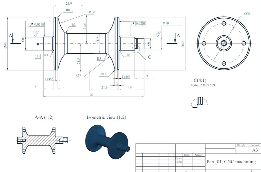
4. Tolérances & Ajuster
Les dessins d'usinage spécifient les dimensions acceptables à travers des tolérances car la fabrication parfaite est rarement possible. Les dimensions non spécifiées ont une tolérance donnée, Les fonctionnalités critiques ont des tolérances spécifiques qui doivent répondre aux exigences spécifiques. Il est important de décider si les pièces devraient avoir un ajustement de dédouanement, ajustement d'interférence, ou ajustement de transition lorsque les assemblages se composent de composants d'accouplement tels que l'arbre et les roulements.
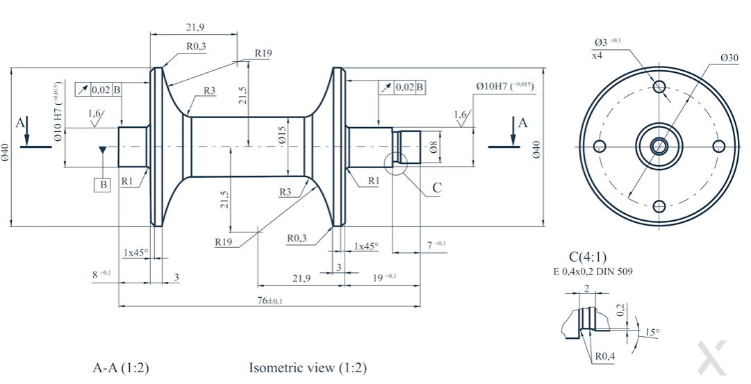
5. Symboles de finition de surface
La finition de surface affecte les performances, esthétique, et les fonctionnalités d'une partie usinée. La PR est la moyenne de standard en matière d'ingénierie pour la rugosité, et la rugosité de surface est spécifiée sur les dessins comme indiqué par des symboles standard. La surface peut être à peu près acceptable s'il s'agit d'une partie structurelle, mais pas le cas pour des pièces mobiles ou des surfaces d'étanchéité. Avec la bonne spécification, Les pièces fonctionnent et répondent aux normes de qualité.
6. Fil & Appel de trou
Le filetage et les trous dans une conception nécessitent des spécifications claires. Les motifs sur un dessin de virage ou d'usinage du moulin montrent le type de thread (métrique m8 x 1.25, Ult ¼ ”-20), profondeur de trou, pas, et d'autres articles tels que les contre-lits ou les contrebores. Par conséquent, Aucun trous ou attaches taraudés ne présentera des erreurs pendant la phase d'assemblage.
7. Sauvetage (Nager)
Sauvetage (Nager) Comprend tous les matériaux, composants, et les sous-ensembles sur lesquels la fabrication a lieu. Cela permet à l'approvisionnement de se procurer les bons matériaux car il fournit les détails critiques tels que le type de matériau, quantité de partie, et les numéros de référence. Spécifiquement pour les assemblages avec de nombreux composants à fabriquer et à assembler exactement, La nomenclature est notre fonctionnalité la plus utile.
Un guide pas à pas pour préparer un dessin d'usinage
Discutons des étapes pour préparer le dessin d'usinage.
1. Définir les exigences de conception
Il est important d'identifier les exigences fonctionnelles de la pièce avant la création du dessin d'usinage. Certaines des exigences incluent des fonctionnalités critiques, sélection des matériaux, tolérances, et finitions de surface. Enfin, Les ingénieurs doivent envisager des contraintes d'usinage car ils devraient considérer qu'il est fabriquée avec un coût et une complexité minimaux.
2. Sélectionner le type de projection
Nous projetons des VIE si l'usinage du dessin en premier angle ou en troisième angle de projection d'angle pour une compréhension facile. Projection de premier angle (Le style en Europe) a la vue de dessus sous la vue avant. La troisième projection d'angle (Utilisé aux États-Unis) est la vue de dessus au-dessus de la vue de la face. Une fois que vous avez choisi la bonne norme de projection, La cohérence dans les dessins devient plus facile à réaliser.
3. Spécifier les dimensions & Tolérances
Après cela, Toutes les dimensions sont ajoutées avec fixe, Mesures explicites sur toutes les dimensions. Utilisation de GD&T (Dimensionnement géométrique & Tolérance) présente le concept qui forme, orientation, et la précision de position doit être définie. La réalisation des tolérances critiques, qui peut inclure des performances, devrait être mis en évidence pour empêcher les écarts d'usinage.
4. Ajouter des annotations & Notes
Exigences de finition de surface, instructions machinables, entre autres choses, des notes supplémentaires telles que le traitement thermique ou les revêtements, etc., doit être inclus. Ces détails garantissent que l'atelier d'usinage et le fournisseur peuvent faire tout ce qui est nécessaire pour fabriquer cette pièce.
5. Valider & Revoir
Afin d'assurer la précision de la dimension, absence de tolérances, ou des annotations peu claires, Un examen approfondi du dessin doit être entrepris avant de finaliser. Un correctement dessiné, La pièce correctement validée signifie que la pièce peut être fabriquée sans interprétation erronée ni reconstruction coûteuse.
Pourquoi les dessins techniques sont-ils toujours importants pour l'approvisionnement en pièces?
Voici quelques raisons pour lesquelles les dessins techniques sont importants pour l'approvisionnement en pièces;
- Fabrication: Les dessins sont une compréhension universelle.
- Application au sein de l'entreprise: Les fournisseurs les utilisent pour donner des estimations de coûts précises quant à ce qu'il en coûtera pour fabriquer.
- Les modifications peuvent être apportées à facilité par les dessins.
- Certaines industries doivent être en mesure de voir des dessins techniques certifiés pour approuver les pièces.
Pourquoi la précision et la précision sont-elles cruciales dans l'usinage des dessins?
La précision et la précision sont l'un des principaux aspects de tout dessin d'usinage CNC;
- Les écarts mineurs peuvent entraîner des problèmes d'assemblage ou fonctionnels, Vous devez donc empêcher la défaillance de la pièce d'assemblage en empêchant la défaillance de la pièce.
- Il doit assurer l'interchangeabilité: Les composants doivent s'adapter parfaitement.
- Les machines CNC sont connues pour faire moins de bien uniquement parce qu'elles dépendent uniquement de l'exactitude de leurs instructions sur la façon de travailler.
- Réduit le temps de coupe et le temps d'usinage: Dessins précis minimiser les déchets de matériaux.
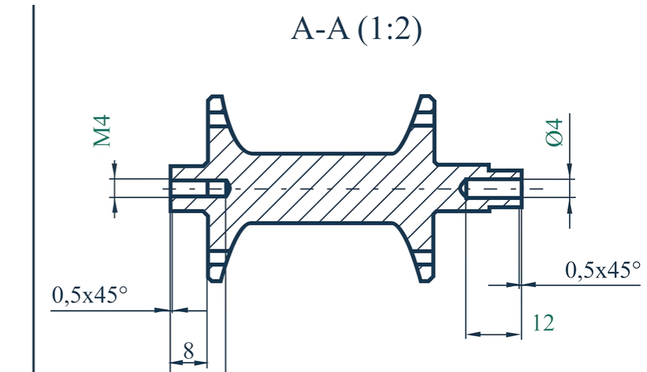
Comment ajouter des threads à un dessin d'usinage
La spécification des trous filetés ou des filetages externes dans les dessins d'usinage CNC doit être détaillé pour un bon alignement de thread. Un dessin technique nécessite six éléments importants pour l'ajout de fil.
1. Spécifier le type de thread
Un dessin d'usinage nécessite une identification de type de thread claire comme sa première étape. La création de fonctionnalités filetées utilise deux normes fondamentales:
- Un ensemble standardisé de spécifications de thread appelé threads métriques a été établi par des normes ISO pour l'utilisation à travers l'Europe et le marché mondial.
- En Amérique du Nord, Les fils USC / UNF apparaissent le plus souvent parce qu'ils respectent les normes ASME.
- La définition du type de thread aide le personnel d'usinage à choisir l'équipement de filetage approprié ainsi que la mesure des instruments tout au long du processus de production.
2. Définir la taille du fil & Pas
Chaque taille et hauteur de fil doit recevoir une notation claire pour éviter la confusion. Une désignation définissant les threads comprend deux valeurs où le premier représente le diamètre et le second indique la mesure de la hauteur. Un fil avec m8 × 1.25 Les dimensions indiquent que le diamètre du thread mesure 8 mm, Et le terrain se trouve à 1.25 mm.
- La mesure du thread spécifie un diamètre de 8 mm comme valeur nominale.
- La distance du filet est équivalent à 1.25 millimètres.
- La mesure de pas dans les fils UNC / UNF est représentée à travers des fils par pouce (TPI) au lieu du système métrique traditionnel. Une désignation de thread de ¼ ”-20 unc indique qu'elle se compose d'un diamètre ¼ de pouce et 20 Threads par pouce.
3. Utiliser des symboles standard
La notation du thread standard maintient la normalisation car elle empêche les mauvaises interprétations de se produire. Les spécifications de thread répertoriées ci-dessous doivent être implémentées:
- OIN 965/1-3 pour les fils métriques
- ASME B1.1 pour les fils unifiés
- Les tolérances du fil, avec les ajustements et les normes de classe, sont définis dans ces spécifications (Les raccords comme M8 × 1,25-6H représentent des fils internes métriques, tandis que ½ ”-13 UNC-2A représente des fils externes unifiés). Les notations de fil appropriées permettent aux machinistes de comprendre correctement le dessin.
4. Montrer la profondeur & Longueur du fil
La profondeur du fil est très critique, Surtout pour les trous aveugles qui ne passent pas tout le long de la partie complète. Le terme m8 × 1.25 – 12 mm de profondeur signifie que le fil pénètre le matériau 12 mm. En outre, Le dessin doit montrer si le fil passe par toute l'épaisseur du matériau ou non. À de rares occasions, Une note telle que Thru ou Full Thread peut être incluse si nécessaire.
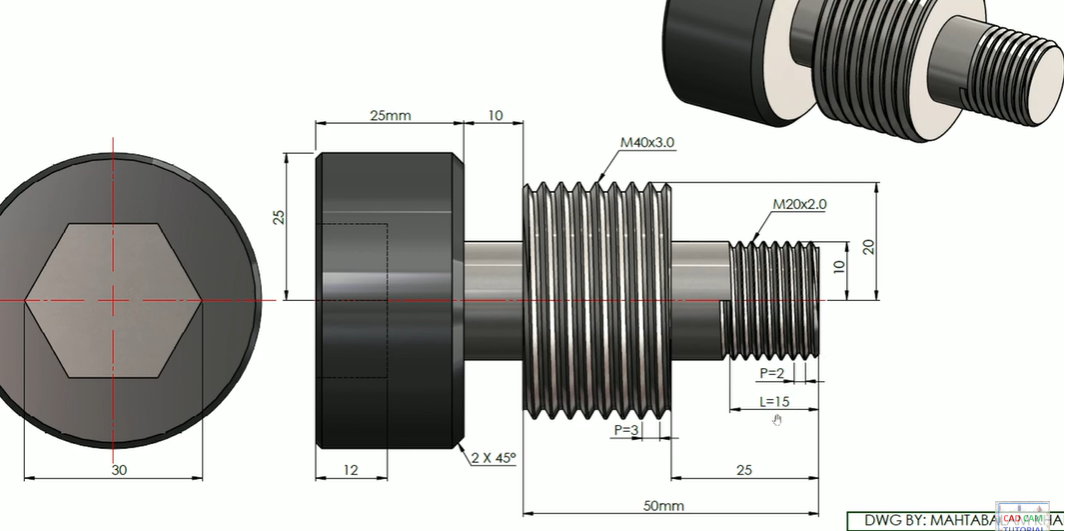
5. Représentation transversale
Pour garantir la clarté, Les threads internes sont affichés par des lignes cachées et des threads externes par des lignes pleines, Comme indiqué dans les vues standard. Lorsque les fils internes doivent être illustrés en détail, comme pour les trous aveugles, Les vues de pièces sectionnelles doivent être utilisées.
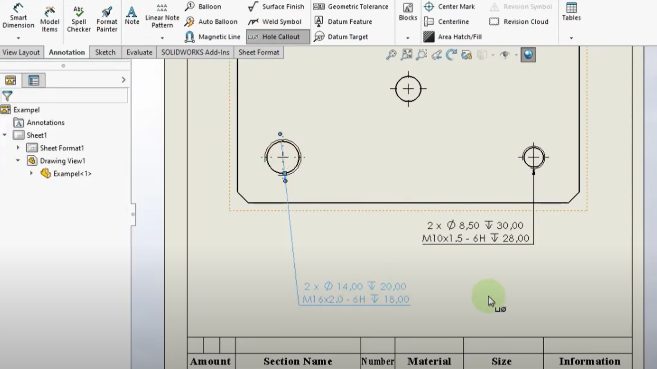
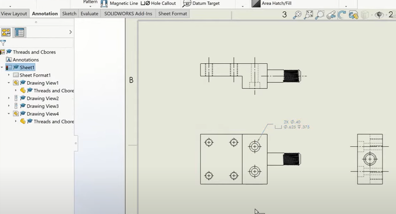
Comment ajouter des appels de trous dans un dessin technique pour CNC?
Il y a des appels de trous appropriés qui doivent être dans des dessins d'usinage CNC pour des spécifications de trous appropriées lors du forage et du taraudage et pour un placement approprié à la ligne d'usinage. Définir correctement les caractéristiques des trous dans un dessin technique:
1. Définir le diamètre du trou
La chose la plus fondamentale à propos d'un appel de trou est son diamètre, Et cela devrait être exprimé en utilisant le ⌀ (diamètre) symbole et dimension. Autrement dit, dans le sens que dans un trou de 10 mm, Le trou a un 10 diamètre mm. Lorsqu'un trou doit être usiné lorsqu'une tolérance stricte est nécessaire (ex: ⌀10 ± 0,05 mm), ils devraient être ajoutés.
2. Spécifier la profondeur
Il y a la nécessité de marquer, que ce soit aveugle ou à travers, un trou. Le trou aveugle ne passe pas complètement par le matériau, et sa profondeur est spécifiée. Ceci est généralement représenté comme:
- ⌀8 mm ⏤ et 15 mm de profondeur (Un trou aveugle avec 15 profondeur mm).
- Une notation de trou est utilisée avec pour des trous à travers, Et cela se fait avec un exemple comme ⌀6 mm à travers, ce qui signifie que les trous à travers la pièce doivent être usinés à travers toute l'épaisseur de la partie.
3. Inclure le type de trou
En outre, Nous spécifions des trous en utilisant différents types, Nous avons donc plus de spécifications.
- Évier de comptoir CCS (Csk) = Race conique pour accueillir des vis à tête plate sous la forme ⌀ 10 MM CSK 90 °.
- Alésage: ⌀10 mm CB ⌀18 mm × 5 mm de profondeur.
- Les trous destinés aux filetages à vis sont appelés taraudage (Enfilé) Trous et indiqué, Par exemple, par M6 × 1.0 (métrique) ou ¼ ”-20 unc (fils unifiés).
4. Positionnement avec GD&T
Afin de positionner les trous précisément pendant l'usinage de précision, DG&T (Dimensionnement géométrique & Tolérance) devrait être utilisé. Les données et les lignes centrales sont satisfaites, donc l'emplacement des trous est relatif. Les écarts acceptables dans le placement du trou peuvent être spécifiés comme tolérance positionnelle de ⌀10 mm ± 0.1 en position vraie Ø0,05 mmc, Par exemple.
Normes communes pour les dessins d'usinage
Donc, Voici les normes communes que nous pouvons utiliser pour l'usinage de dessin:
- OIN (Organisation internationale pour la normalisation) - Normes d'ingénierie mondiales.
- ASME Y14.5 (Société américaine des ingénieurs mécaniques) - GD&Normes t.
- Normes allemandes, Largement utilisé en Europe, sont connus sous le nom de Din (Institut allemand de normalisation).
- Il est (Normes industrielles japonaises)- Normes de fabrication japonaises.
- Bs (Normes britanniques) - Normes britanniques pour les dessins techniques.
Qu'est-ce que le dimension géométrique & Tolérance (DG&T) dans les dessins techniques?
Dimensionnement géométrique & Tolérance (DG&T) est un système standardisé pour le dessin technique. Il aide à définir les dimensions et les tolérances spécifiques à la forme, orientation, taille, et emplacement. mis-à-part, il améliore la fabrication, Améliore la clarté, et permet aux pièces de s'adapter et de fonctionner correctement dans les assemblages.
Pourquoi GD&T important?
- Précis en partie variation de dimension: Il contrôle la variation de la fonction de pièce.
- Il garantit une assemblage approprié, c'est à dire., ajustement fonctionnel.
- Réduit les tolérances étroites inutiles, réduire les coûts.
- Réduit les erreurs, reprise, et les frais d'inspection.
GD clé&T commandes & Symboles
- Rectitude (⏤), Platitude (▭), Circularité (○), Cylindrique (◎).
- Contrôles d'orientation: Parallélisme (∥), Perpendicularité (⊥), Angularité (∠).
- Position (⌖), Concentricité (◎ avec croix), Symétrie (⇔).
- Contrôles du profilems: Petite ligne (∩), Petite surface (⌓).
- Commandes de randonnée: Randonnée circulaire (↗), Randonnée totale (⇈).
Comment GD&T est appliqué
- Un cadre de contrôle des fonctionnalités comprend le type de tolérance, valeur, et les références, Et il contient GD&T symboles placés dedans.
- Par exemple, ⌖ 0.1 | UN | B | C signifie qu'un trou doit être 0.1 mm loin des datums a, B, et c.
Comment les tolérances sont-elles spécifiées sur un dessin d'usinage?
Les variations acceptables des dimensions dans les pièces malinées CNC sont contrôlées par des tolérances. Afin qu'ils puissent vérifier l'ajustement et le fonctionnement des composants appropriés. Le contrôle de la production à travers des notations standard apparaît sur les dessins d'usinage pour spécifier les tolérances.
Tous les types de tolérances courantes, avec l'utilisation des symboles et les plages de valeur standard, apparaître dans le tableau suivant.
Tolérances communes dans les dessins d'usinage
| Type de tolérance | Symbole / Notation | Valeurs typiques |
| Tolérance linéaire | ± x.xx mm (par exemple., ±0,05mm) | ~ ± 0,02 mm à ± 0,1 mm |
| Tolérance angulaire | ± x ° (par exemple., ± 0,5 °) | ± 0,1 ° à ± 1 ° |
| Tolérance limite | ~ X.xx / Y.yy (par exemple., 10.00 / 10.05 mm) | ~ 10.00 / 10.05 mm |
| Tolérance unilatérale | X.xx +0.05/-0.00 mm | +0.02 / -0.00 mm |
| Tolérance bilatérale | ~ X.xx ± 0.05 mm | ± 0,01 mm à ± 0,1 mm |
| Finition de surface | Ra x.xx µm (par exemple., Râ 0.8 µm) | ~ 0.2 µm - 3.2 µm |
| Tolérance à l'ajustement | H7 / G6 (pour les trous / arbres) | H7 (+0.015 / 0.000 mm), G6 (-0.005 / -0.015 mm) |
Gd commun&T tolérances
Dimensionnement géométrique & Tolérance (DG&T) contrôle la partie partie et l'orientation des pièces, ainsi que le positionnement. Le principal GD&T Les tolérances sont constituées de:
| DG&Symbole t | Taper | Exemple de notation |
| ⏤ (Rectitude) | Contrôle | ⏤ 0.02 mm |
| ○ (Platitude) | Contrôle | ○ 0.05 mm |
| ⊥ (Perpendicularité) | Contrôle de l'orientation | ⊥ 0.02 mm à datum a |
| ∥ (Parallélisme) | Contrôle de l'orientation | ∥ 0.03 mm à datum b |
| ⌀ (Position vraie) | Contrôle de l'emplacement | ⌀ 0.05 MM MMC |
| ∩ (Profil d'une surface) | Contrôle du profil | ∩ 0.1 mm |
Considérations clés dans la préparation des dessins techniques
Donc, Voici quelques faits que nous devons garder à l'esprit lors de la préparation des dessins techniques;
- Restez simple: Évitez de rendre les dessins complexes pour que n'importe qui puisse les comprendre.
- Suivez les normes de l'industrie: demeurer par Asme, OIN, ou termes din. La machinabilité des fonctionnalités est vérifiée pour la fabrication de la faisabilité.
- Utilisez des vues sectionnelles et détaillées: Inclure des vues pour les emplacements des fonctionnalités complexes.
- Spécification de la rugosité: Considérez-le si nécessaire sous les exigences de finition de surface.
Quelles sont les applications courantes des dessins d'usinage pour l'usinage CNC?
Voici quelques-unes des utilisations courantes des dessins d'usinage CNC dans plusieurs industries;
- Composants aérospatiaux de haute précision pour les avions et les vaisseaux spatiaux.
- Blocs de moteur, composants de transmission, et les engrenages sont des pièces automobiles.
- Équipement médical: Instruments chirurgicaux et prothèses.
- Machines industrielles: Engrenages, arbres, et outils de précision.
- Logements, cadres, parties micro-macarisées, etc.: Électronique & Robotique
Conclusion
En conclusion, CNC Manufacturing nécessite que Mach Meets soit suivi sous forme de dessins de carnings pour assurer la précision, efficacité, et contrôle de la qualité. Savoir comment leur structure, normes, Et le travail des meilleures pratiques peut avoir un impact énorme sur l'amélioration du processus d'usinage. Cela aidera à produire de meilleures pièces et une production plus lisse. Les dessins d'usinage sont la clé du succès lorsque vous concevez des composants aérospatiaux ou des outils industriels dans tout projet d'usinage CNC.
FAQ
- Quand l'usinage CNC utiliserait-il des dessins d'usinage au lieu de modèles 3D?
3Les modèles D seuls ne peuvent pas contenir de telles informations vitales, cependant, comme tolérances, finitions de surface, et les instructions de fabrication, qui sont fournis dans des dessins d'usinage.
- Comment faire des dessins d'usinage CNC?
Le logiciel CAO utilisé sur cette plate-forme est AutoCAD, Solide, Fusion 360, et Catia.
- Quelle est la différence entre la projection du premier angle et du troisième angle?
En Europe, La projection de premier angle est principalement utilisée aux États-Unis, La projection du troisième angle est la règle. Les deux diffèrent dans le placement des vues.
- Comment rendre mon dessin d'usinage lisible par les fabricants?
Utilisez des conventions standard, et utiliser des annotations claires et évidentes, aussi; Évitez les détails excessifs.
- Les dessins d'usinage sont-ils utilisés pour CNC et l'usinage manuel?
Cela implique que des dessins d'usinage sont appliqués à la fois dans les processus d'usinage CNC et manuels.
![]()

