L'usinage des arbres de moteur est un processus fondamental mais complexe en ingénierie de précision.. Ces arbres servent de composants mécaniques qui transmettent la puissance de rotation d'un moteur à un composant entraîné.. Qu'il soit utilisé dans les véhicules électriques, moteurs industriels, éoliennes, ou du matériel médical, la géométrie d'un arbre moteur, matériel, et la finition de surface influencent directement l'efficacité et la fiabilité du système. Ce guide fournit un aperçu détaillé de l'usinage des arbres moteur., couvrant les types d'arbres, processus, techniques d'usinage, sélection des matériaux, finition, et contrôle de la qualité.
Qu'est-ce que l'usinage d'arbre moteur?
L'usinage de l'arbre moteur est le processus de transformation du stock de métal brut en composants cylindriques de précision capables de transmettre un couple et un mouvement de rotation.. Ces arbres sont usinés selon des tolérances dimensionnelles serrées et des finitions de surface lisses, assurer un fonctionnement fiable sous des charges variables, vitesses, et les conditions environnementales.
En utilisant CNC (Commande numérique par ordinateur) machines, les outils de coupe enlèvent de la matière pour former des éléments clés tels que les diamètres, épaules, rainures, cannelures, et des cônes. La précision est primordiale : des erreurs dans la géométrie de l'arbre peuvent provoquer des vibrations, porter, ou défaillance dans des assemblages critiques.
Types d'arbres de moteur
Les arbres moteur sont disponibles dans une variété de géométries, chacun étant adapté à des applications mécaniques spécifiques:
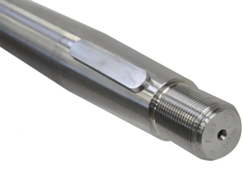
Arbres filetés
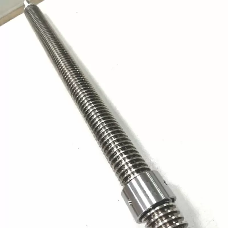
Ces arbres ont des filetages externes à une ou aux deux extrémités, ou sur toute la longueur, leur permettant de servir de fixations ou de connecteurs dans des assemblages. Les arbres filetés sont couramment utilisés dans les actionneurs électriques, entraînements linéaires, et mécanismes de serrage.
Arbres cannelés
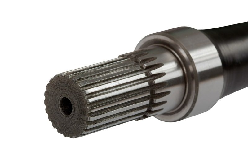
Doté de rainures ou de crêtes longitudinales, les arbres cannelés s'emboîtent avec les composants correspondants pour assurer un transfert de couple sans glissement. Largement utilisé dans les boîtes de vitesses, moteurs d'avion, et transmissions de véhicules, ils permettent un mouvement axial tout en maintenant la synchronisation de rotation.
Arbres creux
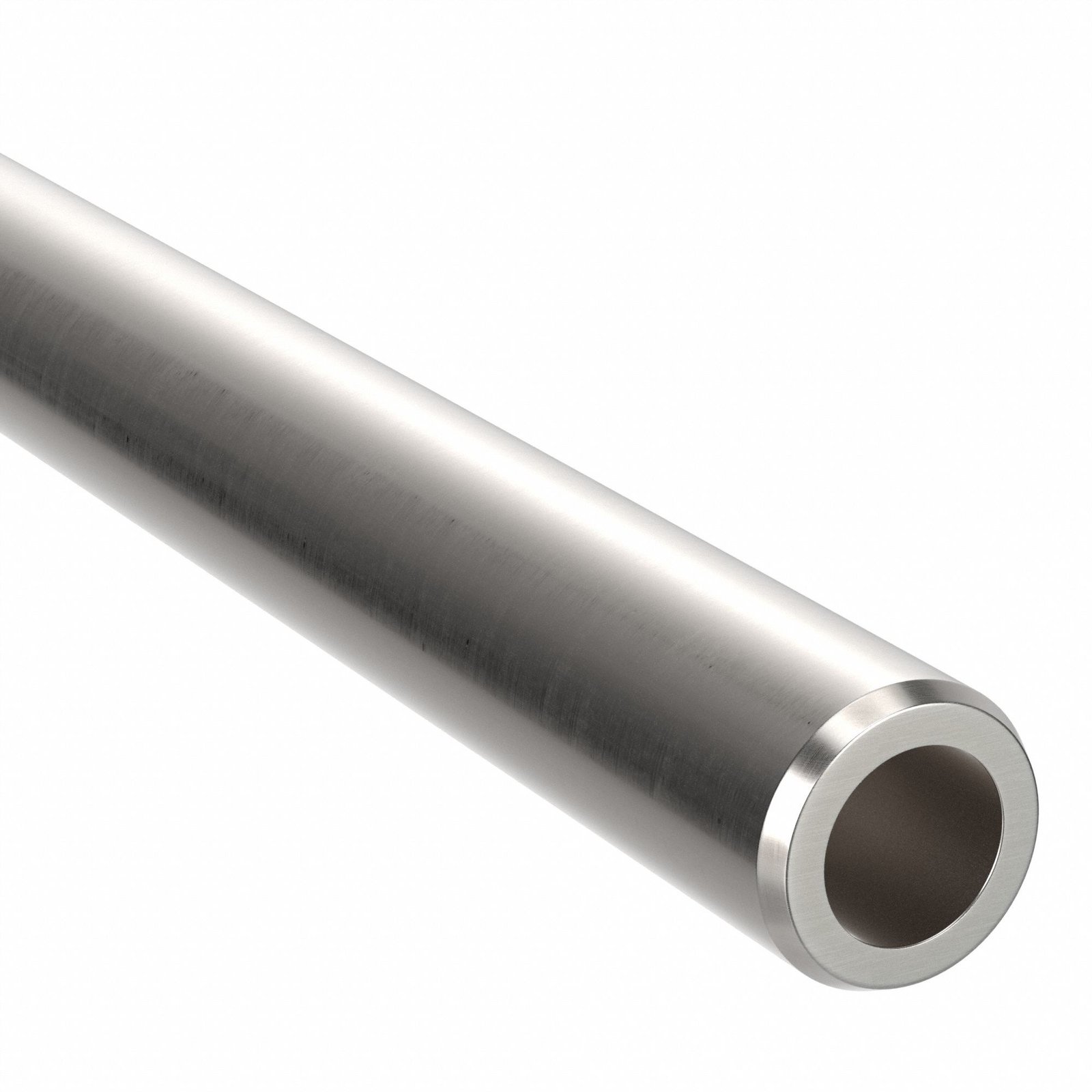
Conçu avec un alésage central, les arbres creux réduisent le poids tout en conservant la résistance. La cavité peut abriter le câblage, canaux de fluide, ou instrumentation. Commun dans l'aérospatiale, robotique, et systèmes d'automatisation, ils réduisent l'inertie et améliorent la réponse.
Arbres à clé
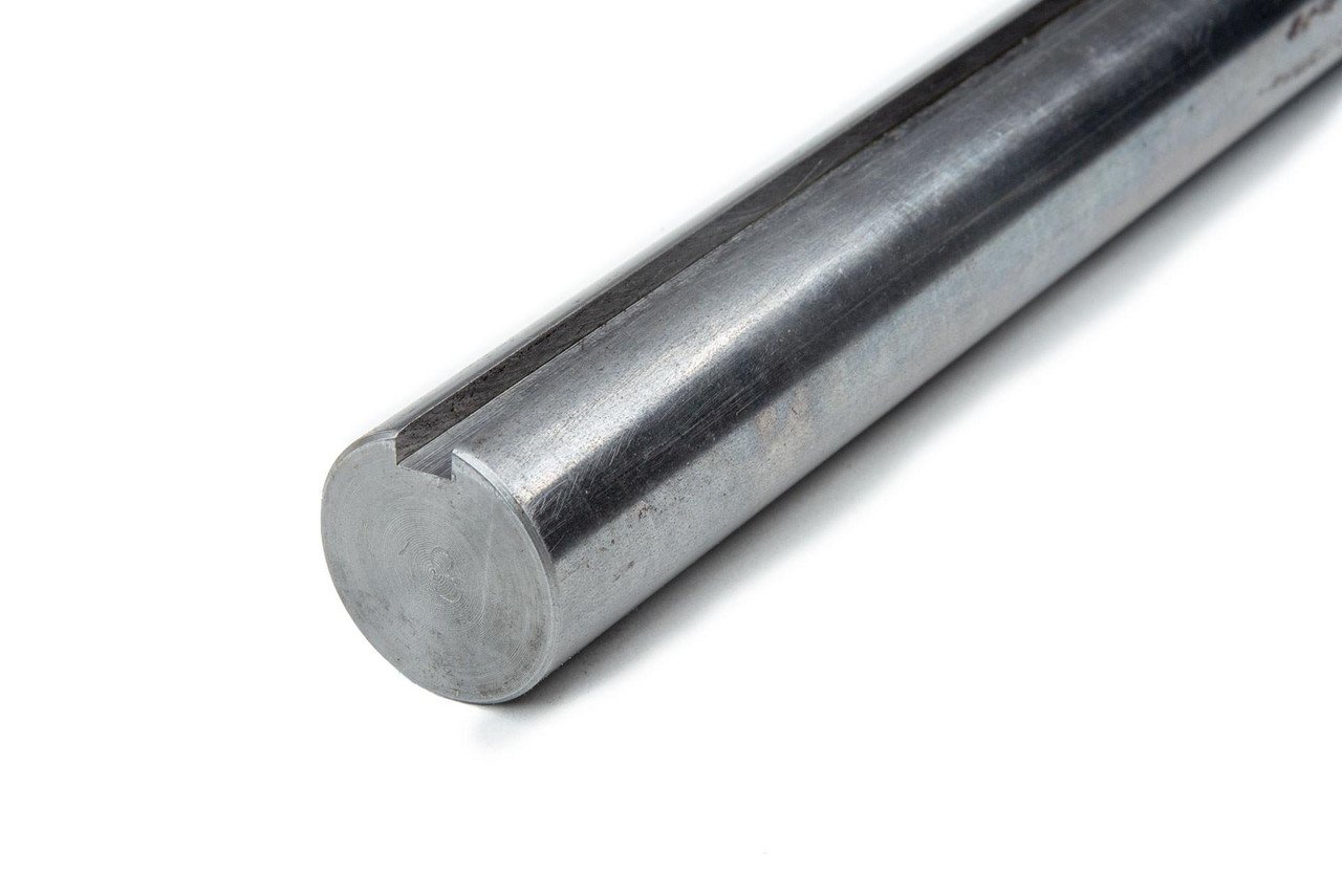
Ces arbres comportent une rainure de clavette longitudinale coupée le long du diamètre extérieur, conçu pour s'adapter à une clé et une rainure correspondantes dans le moyeu correspondant. Cela crée un verrouillage mécanique solide pour la transmission du couple et l'alignement dans les pompes., moteurs, et poulies.
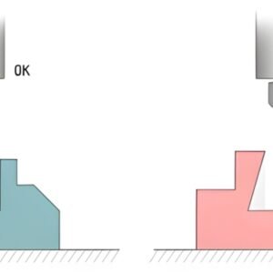
Arbres coniques
Les arbres coniques ont des diamètres qui diminuent progressivement sur la longueur, offrant un ajustement autobloquant avec des composants d'accouplement. Commun dans les moyeux de roue et les volants d'inertie, ils fournissent des connexions sécurisées sans avoir besoin de fixations supplémentaires.
Processus impliqués dans l’usinage des arbres de moteur
Calcul de charge et de couple
Avant le début de l'usinage, les ingénieurs doivent calculer le couple maximum attendu, axial, et charges radiales. Ces valeurs influencent le diamètre de l’arbre, résistance du matériau, et concentrations de stress, s'assurer que la conception répond aux exigences de résistance à la fatigue et de sécurité.
Conception sur CAO
Utiliser un logiciel de CAO comme SolidWorks ou Autodesk Inventor, les ingénieurs créent des dessins 2D détaillés et des modèles 3D. La conception CAO garantit que toutes les exigences dimensionnelles et de tolérance sont spécifiées et permet l'optimisation de la conception avant la production.
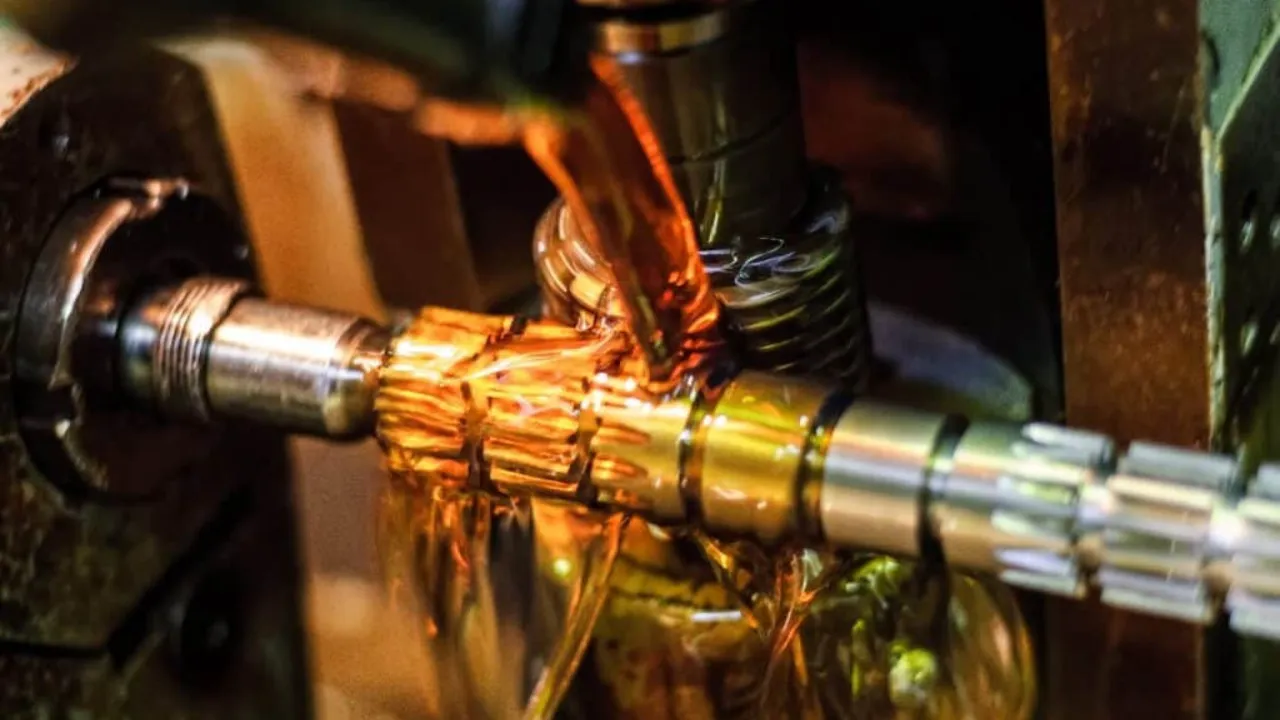
Programmation FAO et usinage CNC
Le modèle CAO est importé dans CAM (Fabrication assistée par ordinateur) logiciel pour générer des parcours d'outils et du G-code. Ce code guide les machines CNC à travers des mouvements précis : tournage, fraisage, forage, ou meulage - pour créer la géométrie de l'arbre finie.
Finition de surface
Post-usinage, les traitements de surface améliorent la précision dimensionnelle, apparence, résistance à l'usure, et protection contre la corrosion. Ces traitements varient en fonction de l'application et du matériau.
Diverses techniques d'usinage CNC dans la production d'arbres de moteur
Tournage CNC
Le tournage CNC est idéal pour produire des éléments concentriques. L'ébauche métallique tourne tandis que des outils de coupe fixes façonnent l'extérieur.. Les opérations courantes incluent faire face, Tournage OD/ID, rainurage, filetage, et tournage conique.
Fraisage CNC
Le fraisage utilise des outils de coupe rotatifs pour former des éléments non cylindriques tels que des méplats., machines à sous, et des claviers. Le fraisage CNC multi-axes permet des géométries complexes et des découpes précises.
Forage CNC
Trous de précision pour les fixations, lubrification, ou le routage des fils sont réalisés à l'aide d'un perçage automatisé. Cela garantit un positionnement précis du trou, diamètres constants, et répétabilité.
Rectification CNC
Le meulage garantit l’état de surface final et la tolérance dimensionnelle (souvent à ±0,002 mm). Les meules abrasives enlèvent un minimum de matière, idéal pour obtenir une concentricité élevée et une faible rugosité de surface (Râ < 0.4 µm).
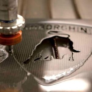
Usinage par décharge électrique (GED)
L'EDM élimine la matière via des décharges électriques, utile pour couper des alliages trempés ou créer des caractéristiques internes complexes qui ne sont pas réalisables avec l'usinage traditionnel. C'est lent mais très précis.
Types de matériaux utilisés dans l'usinage des arbres de moteur
Aluminium
Léger et résistant à la corrosion, aluminium (par exemple., 6061, 7075) est idéal pour les applications à faible charge en robotique, automation, et petits moteurs. Sa haute usinabilité permet également une production rentable.
Acier au carbone
Des notes comme 1045 et 1144 sont économiques et solides. Les arbres en acier au carbone sont largement utilisés dans les machines industrielles où la corrosion n'est pas un problème critique..
Acier inoxydable
Notes 304 et 316 offrent une résistance et une résistance supérieures à la corrosion. Ceux-ci sont souvent utilisés dans la transformation des aliments, marin, et dispositifs médicaux. 316 est plus résistant à la corrosion, alors que 304 est plus rentable.
Acier allié
Les aciers chromoly et autres aciers alliés peuvent être traités thermiquement et extrêmement résistants. Ces matériaux sont choisis pour les applications à fortes contraintes telles que les vilebrequins automobiles et les transmissions lourdes..
Laiton
Avec une excellente usinabilité et résistance à la corrosion, le laiton convient aux applications décoratives ou à faible friction telles que les contacts électriques ou les composants d'instruments.
Titane
Le rapport résistance/poids exceptionnel et la résistance à la corrosion du titane le rendent adapté aux arbres aérospatiaux et marins.. Bien que cher, il fonctionne bien dans des environnements extrêmes.
Alliages de nickel
Les alliages comme l'Inconel résistent à des températures élevées, oxydation, et corrosion. Utilisé dans les turbines à gaz et les moteurs à réaction, ils sont difficiles à usiner mais leurs performances sont inégalées.
Facteurs à prendre en compte lors de l'usinage CNC d'arbres de moteur
Coût des matériaux
Choisissez un matériau qui équilibre les coûts, performances mécaniques, et résistance à la corrosion. L'acier au carbone est économique, tandis que le titane et l'Inconel augmentent considérablement le coût des pièces.
Temps et complexité d'usinage
Arbres aux caractéristiques complexes (cannelures, filetages internes, alésages creux) nécessitent des cycles d'usinage plus longs, augmentation des coûts et du temps de configuration.
Coûts d'outillage
Des outils haut de gamme sont nécessaires pour les matériaux durcis comme l'Inconel. La durée de vie des outils et la fréquence de remplacement affectent les coûts à long terme.
Travail et automatisation
L'automatisation CNC réduit les besoins en main-d'œuvre, mais une configuration et une inspection manuelles sont toujours nécessaires. Les arbres complexes peuvent nécessiter un usinage multi-configurations.
Traitement thermique
Des processus comme le durcissement, tremper, et la nitruration améliorent la résistance à la fatigue et la résistance à l'usure de la surface. Cependant, ils ajoutent des coûts et peuvent nécessiter un usinage supplémentaire après le traitement.
Assurance qualité
Les composants de précision nécessitent une vérification dimensionnelle, mesure de la rugosité d'une surface, et tests de dureté : ces étapes sont essentielles mais prennent du temps.
Processus de finition de surface dans l'usinage d'arbres de moteur
Anodisation
Principalement pour l'aluminium, l'anodisation augmente la résistance à la corrosion et peut être teinte pour une identification visuelle. Il forme une couche d'oxyde durable sur la surface de l'arbre.
Galvanoplastie
Ajoute une fine couche de chrome, nickel, ou du zinc pour la résistance à la corrosion, porter des protections, et esthétique.
Phosphation
Crée une couche de phosphate cristallin sur les surfaces en acier pour résister à la corrosion et favoriser l'adhérence de la peinture.
Passivation
Utilisé pour les arbres en acier inoxydable pour éliminer la contamination par le fer, améliorant la résistance à la corrosion en formant une couche superficielle passive riche en chrome.
Nitruration
Diffuse l'azote dans les surfaces en acier allié, produire un boîtier rigide avec une distorsion minimale. Idéal pour les applications à forte usure comme les arbres de transmission.
Projection thermique
Une méthode de revêtement haute performance où des matériaux fondus sont pulvérisés sur l'arbre, améliorer l'usure, chaleur, et résistance à la corrosion sans altérer les dimensions de la base.
Contrôle qualité dans l’usinage des arbres moteurs
Contrôle dimensionnel
Les dimensions critiques sont vérifiées à l'aide de MMT, micromètres, et des jauges pour assurer le respect des tolérances (généralement ±0,01 mm ou plus).
Test de rugosité de surface
Des profilomètres ou des testeurs tactiles sont utilisés pour vérifier les valeurs Ra, spécialement pour les surfaces d'appui ou les interfaces d'étanchéité.
Vérification du matériel
Spectrométrie, essai de dureté, et les tests de traction garantissent la qualité et les propriétés correctes du métal de base.
Documentation et traçabilité
Tenue des dossiers d'usinage, certifications matérielles, et les rapports d'inspection aident à suivre la qualité de la production et à satisfaire aux normes réglementaires.
Inspection visuelle et des défauts
Les arbres sont inspectés pour détecter les rayures, fouillis, marques d'outils, ou anomalies de surface qui pourraient avoir un impact sur les performances.
Conclusion
L'usinage des arbres moteurs est une pierre angulaire de la conception et de la production mécaniques, jouer un rôle essentiel dans les systèmes de rotation dans presque tous les secteurs. De la conception et de la sélection des matériaux à la finition et au contrôle qualité, chaque étape doit être exécutée avec précision et souci du détail.
À Précision au sommet, nous sommes spécialisés dans la production d'arbres de moteur répondant aux normes de précision les plus élevées, performance, et durabilité. Contactez-nous dès aujourd'hui pour obtenir des conseils d'experts ou pour demander un devis d'usinage personnalisé adapté aux besoins de votre application..
FAQ
1. Pourquoi la concentricité est-elle la tolérance géométrique la plus critique pour les arbres de moteur?
La concentricité est primordiale car la fonction d'un arbre moteur est purement rotationnelle., transmission du couple à des vitesses élevées. Une mauvaise concentricité signifie que l’axe central de l’arbre est mal aligné avec son axe de rotation, conduisant à:
-
Vibrations sévères: Provoque du bruit et un déséquilibre dynamique.
-
Usure des roulements: Défaillance prématurée des roulements due à une charge inégale.
- Efficacité réduite: Perte de puissance et production de chaleur.
Les fabricants utilisent souvent le meulage CNC comme processus final pour garantir que la concentricité et la tolérance de diamètre respectent les spécifications requises au niveau du micron..
2. En quoi les arbres clavetés et les arbres cannelés diffèrent-ils en termes de transmission du couple?
Les deux types transfèrent le couple sans glissement, mais ils diffèrent par l'engagement et la répartition de la charge:
-
Arbres à clé: S'appuyer sur un seul rainure et clé pour verrouiller le hub, concentrer la charge et la contrainte en un seul point, qui convient aux applications à couple modéré.
-
Arbres cannelés: Fonctionnalité multiple rainures longitudinales (cannelures), répartir la charge de couple uniformément sur une surface beaucoup plus grande. Cela permet aux arbres cannelés de gérer considérablement charges de couple plus élevées et offre une plus grande précision d'alignement, ce qui les rend courants dans les transmissions lourdes.
3. Pourquoi les arbres creux sont-ils préférés aux arbres pleins dans les applications hautes performances comme la robotique?
Les arbres creux sont préférés car ils sont considérablement réduire l'inertie de rotation tout en conservant souvent une résistance suffisante. La réduction de l'inertie permet au système moteur (notamment en robotique ou en automatisation) à accélérer, ralentir, et inverser la direction plus rapidement et avec moins d'énergie. En plus, l'alésage central fournit un canal pratique pour acheminer le câblage interne, capteurs, ou conduites de fluide sans interférence externe.
4. Quel processus de finition est utilisé pour améliorer la dureté de surface et la résistance à la fatigue des arbres en acier allié?
Nitruration est le processus de finition clé. La nitruration consiste à diffuser de l'azote dans la surface de l'acier allié à des températures élevées.. Cela crée un difficile, résistant à l'usure profondeur du boîtier sans avoir besoin de trempe, provoquant ainsi distorsion dimensionnelle minimale. Cela le rend idéal pour les zones à forte usure telles que les tourillons ou les surfaces d'engagement des engrenages., améliorant considérablement la durée de vie de l'arbre sous chargement cyclique.
5. Pourquoi l'usinage par électroérosion (GED) parfois utilisé dans la production d'arbres de moteur malgré sa lenteur?
L'EDM est utilisé exclusivement lorsque la fonction requise ne peut pas être usinée à l'aide de méthodes conventionnelles en raison de dureté du matériau ou complexité de la géométrie. Il est souvent utilisé pour:
-
Couper des rainures ou des fentes dans des arbres en acier allié déjà entièrement trempés.
- Créez des caractéristiques internes complexes ou des micro-trous précis sans introduire de contrainte mécanique.
L'EDM enlève de la matière par érosion par étincelle, rendant le processus lent mais capable d’une extrême précision quelle que soit la dureté du matériau.
6. Comment se déroule le choix de la nuance d'acier inoxydable (304 contre. 316) application d'arbre d'impact?
-
304 Acier inoxydable: Offre une bonne résistance à la corrosion, excellente machinabilité, et est généralement plus rentable. Il convient à l'industrie générale, nourriture, et applications non marines.
-
316 Acier inoxydable: Contient molybdène, ce qui fournit de manière significative Résistance à la corrosion supérieure, notamment contre les chlorures, eau salée, et acides forts. C'est le préféré, quoique plus cher, choix pour la marine, pharmaceutique, et puits de traitement chimique.
7. Quel rôle jouent les tests de rugosité de surface (Valeurs RA) jouer dans le contrôle qualité de l'arbre moteur?
Test de rugosité de surface, mesurant généralement la rugosité moyenne ($Ra$), est essentiel car la surface de l’arbre interagit directement avec les roulements et les joints.
-
Faible Ra (finition lisse): Indispensable pour tourillons pour minimiser les frottements, génération de chaleur, et usure du roulement.
-
Ra contrôlé: Critique pour surfaces d'étanchéité (où l'arbre passe à travers un joint) pour garantir que le joint conserve son intégrité sans user rapidement la lèvre. Une rugosité trop élevée ou trop faible peut provoquer une défaillance. Les exigences typiques en matière de Ra pour les surfaces d'appui sont souvent inférieures à 0.4 µm.
![]()