

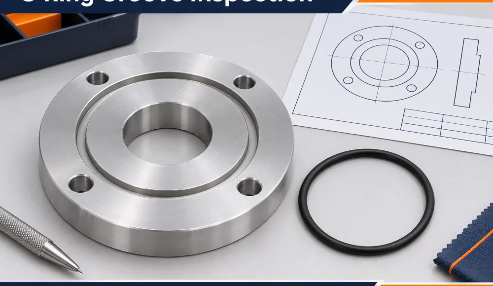
O-ring groove inspection should verify the geometry, état de surface, and finished state specified for your CNC part. Groove width alone cannot establish sealing performance. Agree critical features, measurement access, and acceptance records before production. Validate the complete assembly against its service requirements.
Start With The Approved Seal Arrangement
Your inspection plan must identify the intended seal arrangement and the drawing requirements that apply to it.
Distinguish a face groove from a radial groove in a shaft or bore. Identify whether the application is static or dynamic.
Parker’s O-Ring Handbook separates these arrangements and their design recommendations. Do not transfer dimensions between applications without design approval.
Specify the mating component, seal size, compound, and approved drawing revision. The machinist needs the released geometry, not an instruction to “fit an O-ring.”
For the broader manufacturing process, notre grooving machining guide explains common groove operations. This inspection guide focuses on acceptance of the sealing features.
Inspect The Complete Groove Geometry
You should check the groove dimensions and their relationship to mating features rather than accepting one isolated width measurement.
For a face groove, define depth relative to the specified face or datum. For a radial groove, review the relevant diameters and their relationship.
The final gland space depends on the assembled geometry. A component groove measurement does not replace the mating-part tolerance review.
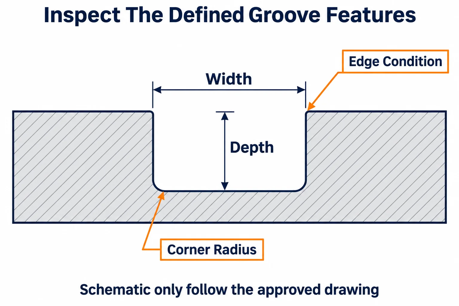
| Fonctionnalité | What The Inspection Plan Should Resolve |
|---|---|
| Groove width | Measurement location, limites, and any permitted variation |
| Depth or groove diameter | Reference surface, calculation method, et limites d'acceptation |
| Groove position | Relationship to the specified axis, affronter, or datums |
| Corner radii | Required profile and how it will be assessed |
| Entry edges and lead-ins | Permitted edge condition and assembly protection |
| Surfaces de contact | Their specified dimensions, finition, and geometric relationships |
Keep the profile requirements on the controlled drawing. Do not replace a specified radius with a general deburring instruction.
Review Surface Condition Along The Seal Path
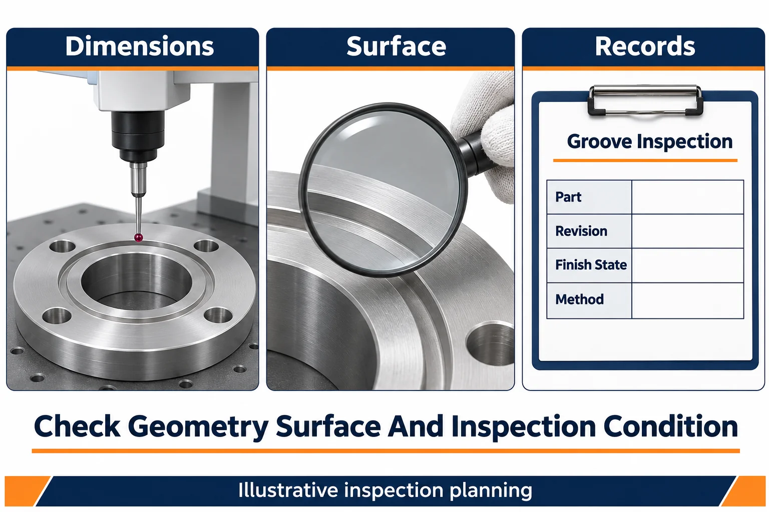
Your surface acceptance should address texture and local damage on the specified sealing surfaces.
Trelleborg’s O-Rings and Back-up Rings catalog explains that Ra alone cannot fully assess sealing surface quality. It also discusses scratches and machining scores.
Identify the surfaces requiring roughness measurement. State the parameter, unités, measurement direction, and evaluation conditions required by your specification.
Define acceptance for burrs, dents, rayures, and other localized defects. An acceptable average roughness reading can coexist with unacceptable local damage.
Use agreed lighting and magnification for visual checks where needed. A photograph can support a record but may not resolve a small defect’s depth.
Do not assume polishing is an approved repair. Material removal can change the groove profile or dimensions.
Confirm That The Measurement Method Can Reach The Feature
Your supplier should demonstrate that the proposed method can assess each critical groove feature without obstructed contact or visibility.
Review narrow groove floors, internal bores, and undercuts before selecting the inspection route. Check the actual probe or optical access.
A convenient external caliper reading may not address the required internal profile. Ask which feature each reported value represents.
Agree how radii and edge conditions will be evaluated. If a replica or sectional sample is proposed, approve its purpose and limitations.
For difficult features, request an initial inspection demonstration before the production order. Retain the method and setup with the approved plan.
Inspect The Specified Finish And Cleanliness State
Your final acceptance should identify whether the groove is measured before or after coating, finition, and cleaning.
List any intermediate machining checks separately. If the drawing applies to the finished component, an earlier measurement needs an agreed relationship to final acceptance.
Confirm masking, coating coverage, and any permitted changes to sealing surfaces. Review the processing sequence before the first production lot.
Inspect for debris and handling damage after final cleaning. Protect the groove during packing and assembly preparation.
If rework changes the surface or geometry, define which inspections must be repeated. Preserve the connection between the reworked part and its records.
Separate Groove Conformity From Assembly Sealing Validation
A conforming groove supports the seal design, but it does not independently demonstrate that the complete assembly meets its requirements.
Seal behavior also depends on the mating parts, elastomer, assembly condition, and service environment. Define functional validation separately.
Agree any leak, pression, température, mouvement, or exposure testing required for the assembly. Use conditions approved for the actual application.
Do not accept a successful assembly test as permission to ignore an out-of-tolerance groove. inversement, a dimensional report alone cannot prove every service condition.
| Release Evidence | Question It Answers |
|---|---|
| Component inspection | Does the machined part meet the released requirements |
| Surface review | Are the required sealing surfaces in the accepted condition |
| Material and finish records | Was the agreed component processing route followed |
| Assembly validation | Does the complete assembly meet the specified functional tests |
Request Quotes With The Same Inspection Scope
Your quotation should include groove machining, finition, measurement access, surface checks, and the required delivery records.
TOPS fournit Services d'usinage CNC. Send the mating geometry and groove requirements with your drawing so manufacturing and inspection can be reviewed together.
Identify the critical features and required reporting coverage. Confirm who owns seal design approval and any assembly validation.
Costs depend on geometry, accès aux outils, matériel, finition, quantités, measurement method, and reporting scope. Avoid comparing different acceptance assumptions.
Questions fréquemment posées
You should resolve groove geometry, surface acceptance, and verification responsibilities before ordering production parts.
Can Groove Width Alone Establish Acceptance
Non. Check all drawing requirements, including depth or diameters, position, profil, and specified surface condition.
Does A Good Ra Reading Prove A Suitable Sealing Surface
Non. Local damage and machining scores require separate consideration under the approved surface criteria.
Can The Same Groove Dimensions Be Used For Every O Ring
Non. The arrangement, seal selection, géométrie d'accouplement, and application requirements determine the approved design.
Should Inspection Take Place Before Or After Coating
Follow the drawing and approved manufacturing route. Identify which checks apply to the final delivered condition.
Can Polishing Correct A Rejected Groove
Only under an approved rework plan. Recheck the affected geometry and surface requirements afterward.
Does A Dimensionally Correct Groove Guarantee No Leakage
Non. Validate the complete assembly using the specified seal, pièces d'accouplement, installation, and functional requirements.
Request A Groove Machining And Inspection Review
Contactez-nous avec votre CAO, dessin, matériel, finition, quantités, and critical groove requirements. Include mating geometry and required inspection records. Agree the measurement route and final acceptance condition before production approval.