



G コードは、テキストベースの CNC プログラミング形式の一般的な名前であり、機械に軸の位置決めと移動方法、および加工操作の実行方法を指示します。. 完全な CNC プログラムでは、M コードと X などのアドレス ワードも使用します。, Y, Z, F, S, そしてT. このガイドではその仕組みについて説明します, その種類, そしてそれが使用される場所.
Gコードとは何ですか?
G コードは、CNC マシンの動作と操作を制御するテキストベースの形式の一般名です。.
厳密に言えば, パートプログラムには数種類の単語が含まれています. G ワードは通常、準備モードと動作モードを定義します。. M ワードはさまざまなマシン機能を処理します. S は主軸速度を設定します, F セットフィード, および T アドレス ツール. 文字セットの位置を調整する.
最新の G コード規則は、歴史的な RS-274 フォーマットと ISO に根ざしています。 6983 標準ファミリー. 実際の実装はコントローラーと工作機械メーカーによって異なります.
Gコードはどのように機能するのか?
CNC はプログラムブロックを順番に解釈します。, 多くの場合、機械軸に命令を与える前に先読みと軌道計画を使用します。.
ブロックはプログラム命令の 1 行です。. 各ブロックには住所文字と数値からなる単語が含まれています. 文字は数字の意味を定義します.
- Gワードは操作を設定します, ストレートカットの場合はG01など.
- バツ, Y, と Z セット座標.
- F は送り速度を設定し、S は主軸速度を設定します.
- T は工具を選択し、M は機械の機能を設定します.
一部のコマンドはモーダルです. モーダル コマンドは、変更またはキャンセルするまでアクティブなままになります。. G01, G21, G90, および G54 は一般的なモーダルの例です.
これはブロックの例です:
G21 G90 G54 G01 X50.0 Y25.0 F250
コードの意味と許容される組み合わせはコントローラによって異なります. この記事の例では、一般的なファナック スタイルの規則を使用しています。.
G コード プログラムとはどのようなものですか?
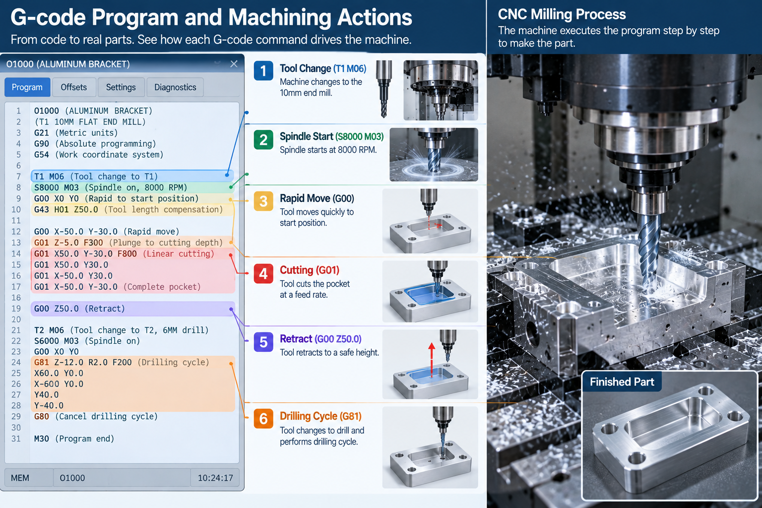
G コード プログラムは、安全な開始からプログラムの終了まで実行される一連のブロックです。.
G21 G17 G90 G40 G49 G80
G54
T1 M06
S8000M03
G00 X0 Y0 Z5
G01 Z-2 F150
G01 X50 F300
G00 Z5
M05
M30
生産プログラムでは通常、セーフスタート ブロックを使用して、加工開始前に不要なモーダル状態をキャンセルします。.
G コードのワードとアドレスとは何ですか?
単語はアドレス文字の後に値が続くものです. 文字は値に意味を与えます.
| 住所 | 共通の意味 |
| g | 準備または動作機能 |
| M | その他の機械機能 |
| バツ, Y, Z | 軸座標 |
| 私, j, K | 多くのコントロールの円弧中心オフセット |
| R | 半径または周期パラメータ, 文脈に応じて |
| F | フィードレート |
| S | 主軸速度 |
| T | ツールの選択 |
| N | シーケンス番号またはブロック番号 |
| H | 多くの制御装置の工具長オフセット レジスタ |
| D | 多くのコントロールにあるカッター補正レジスター |
円形移動では一般的に I が使用されます, j, K 中心オフセットまたは R 半径値, コントローラとプログラミング方法に応じて.
モーダルコマンドと非モーダルコマンドとは?
モーダル コマンドは、変更またはキャンセルされるまでアクティブのままです. 非モーダル コマンドは、それを含むブロックにのみ適用されます.
通常、一度にアクティブになるコマンドは同じモーダル グループから 1 つだけです. G00 と G01 が相互に置き換えられます. G90 と G91 は相互に置き換えられます. G17, G18, と G19 が相互に置き換えられます.
モーダル グループを理解すると、短いプログラムで長い一連の動きを制御できる理由が説明されます。.
G コードの一般的な種類
CNC パート プログラムには G 関数が含まれています, M 関数, 言葉をコーディネートする, 送りおよび主軸コマンド, ツールデータ, とオフセット.
G 機能はモーションと動作モードを設定します. M 機能はスピンドルなどの補助機械の動作をトリガーします, クーラント, そしてプログラムの流れ.
| グループ | 例 | 目的 |
| モーション | G00, G01, G02, G03 | 位置決めとカット動作 |
| 単位とモード | G20, G21, G90, G91 | インチまたはミリメートル, 絶対的または増分的 |
| 平面とオフセット | G17-G19, G54-G59 | 平面の選択と作業オフセット |
| 補償 | G40, G41, G42, G43, G49 | カッターと工具の長さの補正 |
| 固定サイクル | G81, G83, G84 | 掘削, ペックドリリング, たたく |
| マクロとプローブ | G65 およびコントローラー固有のサイクル | 再利用可能なルーチン, 測定, オートメーション |
マクロ構文とプローブ サイクルは、コントローラとプローブ システム間で大幅に異なります.
一般的な G コードと M コード
次のコードは、ファナック スタイルおよび互換性のある制御に共通です。. 必ずコントローラーのマニュアルを確認してください.
| コード | 関数 |
| G00 | 高速測位 |
| G01 | 線形補間 |
| G02 | 円弧補間, 時計回りに |
| G03 | 円弧補間, 反時計回り |
| G04 | 住む |
| G17 / G18 / G19 | 平面の選択 |
| G20 / G21 | インチ / 多くのコントロールではミリメートル単位 |
| G28 | 基準位置復帰, コントローラー固有の動作 |
| G40 / G41 / G42 | カッター補正オフ / 左 / 右 |
| G43 | プラスの工具長補正, H オフセット レジスタと一緒に使用 |
| G49 | 工具長補正のキャンセル |
| G54-G59 | ワーク座標オフセットとシステム |
| G81 / G83 / G84 | 掘削 / ペックドリリング / タッピングサイクル |
| G90 / G91 | 絶対 / インクリメンタル位置決め |
| G94 / G95 | 1分あたりのフィード / 1回転あたりの送り量 |
| コード | 関数 |
| M00 | プログラム停止 |
| M01 | オプションの停止 |
| M03 / M04 | スピンドルは時計回り / 反時計回り |
| M05 | 主軸停止 |
| M06 | 工具交換 |
| M08 / M09 | クーラントオン / オフ |
| M30 | プログラムの終了とリセット |
M コードの動作は特にマシン ビルダーに依存します。. クーラント, パレットチェンジャー, ドア, クランプ, チップコンベアはマシン固有の M 機能を使用する場合があります. 詳細については、ガイドをご覧ください。 Mコード.
多くのマシニングセンターで, T ワードはツール番号を事前選択または呼び出します, 一方、M06 は実際の工具交換を指示します。.
絶対位置決めと増分位置決め
G90 と G91 は、コントロールが座標を読み取る方法を変更します.
- G90 絶対位置決め: 座標はアクティブなワーク座標の原点から測定されます.
- G91 インクリメンタル位置決め: 各座標は現在位置から測定されます.
ほとんどのプログラムは明確にするために絶対位置を使用します。, その後、パターンを繰り返す場合はインクリメンタルに切り替えます.
機械座標, ワークオフセットとツールオフセット
機械座標は機械参照系に関連付けられています. 作業座標により、その機械空間内の部品の位置が特定されます。. 工具オフセットは工具の長さと半径を考慮します。.
- G54 ~ G59 はパーツのワーク座標系を設定します.
- G43 は、H レジスタを使用して正の工具長補正を適用します, G43 H01 Z50など.
- G41 と G42 は、多くのコントロールで D レジスタを使用してカッター補正を適用します.
- G49 は工具長補正をキャンセルします.
この階層により、部品がテーブル上で移動する場合でもプログラムの移植性が保たれます。.
G コードの方言と標準
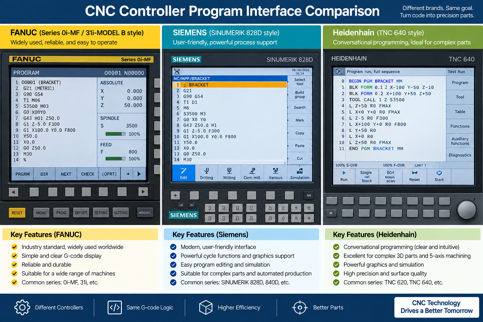
共通のコアが存在する, しかし、すべての CNC コントローラーには独自の方言があります.
ISO 6983 と RS-274 は共通の基盤を定義します. ファナックベースの方言が広く使用されている, 一方シーメンス, ハイデンハイン, 小さい, 他のコントロールは独自の構文を使用します, サイクル, 拡張子, およびコントローラー固有の機能.
一部の機能, プロービングや高速加工など, コントローラー固有のものです. あるマシン用に書かれたプログラムが別のマシンでは実行できないのはこのためです。. 馴染みのないコードを使用する前に、必ずコントローラーのマニュアルを確認してください。.
Gコードはどのように作成されるか?
複雑な制作プログラムは通常、CAM ソフトウェアで生成されます。, ただし、すべての G コードが CAM から来ているわけではありません.
- CAM ツールパスは CAD モデルから生成されます.
- 単純な部品は制御装置で手動でプログラム可能.
- 会話型コントロールにより、オペレーターはプロンプトを使用してサイクルを構築できます.
- マクロとパラメトリック プログラムにより、繰り返しの作業を自動化します.
- セットアップには手書きのコードが依然として重要, 編集, トラブルシューティング.
ガイドを参照してください GコードとMコードを使用したCNCプログラミング言語.
CAM ポストプロセッサーとは?
ポストプロセッサは、CAM ツールパスを特定のマシン コントローラーが期待する G コード言語に変換します。.
コントローラー間の違いを処理します, サイクルフォーマットを含む, オフセット, およびマシン固有の機能. 1 つの部品を別の機械で加工する場合、適切なポストプロセッサが不可欠です. ガイドを参照してください CNC加工用のCADファイル.
G コードが使用される場所?
G コードはほとんどの CNC 工作機械とその他のいくつかのモーション システムを駆動します.
- ポケットのCNCフライス加工, 輪郭, そして顔.
- シャフト用CNC旋削加工, スレッド, と直径.
- CNC EDM システム, コントローラ固有の構文による電極またはワイヤの動作に数値制御プログラムを使用する.
- レーザ, プラズマ, そしてウォータージェット切断.
- 多くの FDM/FFF 3D プリンター, モーションに G コードまたは関連する方言を使用する, 押し出し, ヒーター, そしてファン.
機械加工サービスについて, 私たちのを参照してください CNCフライス加工 そして CNC旋削加工 ページ.
G コードと CAD および CAM
典型的な現代のワークフローでは, CAD による形状の定義, CAMはツールパスを作成します, ポストプロセッサはマシン固有の CNC コードを出力します。.
| ステージ | 主な役割 | 出力 |
| CAD | パーツのジオメトリを定義します | 2Dまたは3Dモデル |
| カム | 加工戦略とツールパスを作成します | ツールパスデータ |
| ポストプロセッサ | マシンとコントロールのツールパスを変換します | CNCプログラム |
| CNCコントローラー | プログラムを解釈して動作を制御します | 機械の動き |
単純な部品は、個別の CAM ワークフローを使用せずに手動または会話によってプログラムすることもできます。. ガイドを参照してください CADとは何ですか.
制限とリスク
G コードは強力だが容赦がない. 1 つのエラーが機械をクラッシュさせたり、部品を廃棄したりする可能性があります.
- コントローラーごとに方言が異なる.
- 間違ったオフセットまたはツールデータにより位置エラーが発生する.
- 1 つのタイプミスでツールがフィクスチャに送り込まれる可能性があります.
- G コードには物理セットアップを認識する機能が組み込まれていません.
- 従来の G コードは主に動きと状態を記述します, 設計意図ではない. コントロールは、一連の動作がポケットを表すかどうかを知りません。, ボス, またはシール面.
複雑なツールパスは通常、CAM を通じて生成および検証されます。, シミュレーション, およびマシン固有の証明.
G コードの検証とベスト プラクティス
これらの習慣によりリスクが軽減され、マシンが保護されます.
- プログラムを実行する前にシミュレーションする.
- 機械メーカーが承認したシミュレーションを使用する, グラフィックス, 予行演習, マシンロック, シングルブロック, 必要に応じてプロシージャをオーバーライドします.
- ワーク保持力の確認, ツール, オフセット, クリアランスプレーン, 走行前の移動制限.
- セーフスタート ブロックを使用して不要なモーダル状態をキャンセルする.
- 制御された条件下で最初の部分の証明を実行する.
- プログラムを読みやすくするためのコメント ブロック.
- 実績のあるプログラムのバックアップとバージョン管理を維持します.
よくある質問
G コードはどのマシンでも同じですか?
いいえ. 共通の核がある, ただし、各コントローラーには独自の方言があります.
GコードとMコードの違いは何ですか?
G 機能はモーションと動作モードを設定します. 主軸などの機械動作を制御するM機能, クーラント, そしてプログラムの流れ.
CNC マシンを実行するには G コードを学ぶ必要がありますか??
CAM はほとんどのコードを生成します, ただし、G コードを読み取るとセットアップに役立ちます, オフセット, トラブルシューティング.
初心者が最初に学ぶべきGコードは何ですか?
一般的な開始コードには、直線運動の G00 および G01 が含まれます。, 円弧用の G02 および G03, G17-G19 飛行機用, G54-G59 ワークオフセット用, 位置決め用の G90 および G91, G81 などの固定サイクル. 正確なコードはコントロールによって異なります.
Gコードは3Dプリントに使用できますか?
はい. 多くの FDM/FFF プリンタは G コードまたは関連する方言を使用しています.
ポストプロセッサーとは?
CAM ツールパスを、特定のマシン コントローラーが期待する G コード言語に変換します。.
GコードはCNCマシンをクラッシュさせることができますか?
はい. 間違った座標, オフセット, ツールデータ, モーダル状態, または急速な動きは衝突を引き起こす可能性があります. プログラムは本番前にシミュレーションして検証する必要があります.
Gコードを手動で記述できますか?
はい. 簡単なパーツや編集は手動でプログラム可能. 複雑な 3D ツールパスは通常、CAM を使用して生成されます.
CNC 加工のガイダンスを取得する
3Dモデルを送信してください, 2D図, 材料, 量, および公差要件. 当社のエンジニアは設計を検討し、見積もりの前に適切な加工プロセスを推奨します。.


3 』への思いGコードとは何ですか? 意味, 関数, 種類と用途”