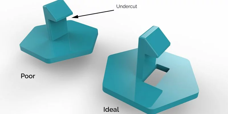
Undercuts are one of the most challenging aspects of plastic injection molding design. They are the features that prevent a molded part from being ejected in a simple straight-pull mold—typically because the geometry locks the part within the tool.
In injection molding, an undercut can take many forms: a side hole, a groove, a recess, or a protruding hook. These features often add essential functionality—such as fastening, sealing, or alignment—but they also make mold construction more complex.
Common examples include:
The threads on a plastic fastener.
A slot for a power button on a device case.
Locking tabs on a taillight lens.
Angled bosses or grooves in mechanical housings.
While undercuts are often unavoidable, they can be managed through smart engineering. The following six methods show how to design and mold parts with undercuts efficiently—without sacrificing quality or driving up costs.
1. Adjusting the Parting Line
Shifting the mold’s parting line is often the easiest way to accommodate undercuts.
By modifying the mold’s orientation or parting geometry, you can position the undercut so that it aligns with the parting line. This allows it to be formed by the two mold halves and released cleanly upon ejection.
Example:
If your part includes side standoffs or small bosses, moving the parting line and adjusting the draft angles may eliminate the need for additional mechanisms.
Advantages:
Simplifies tooling and maintenance.
Reduces cost compared to side-actions.
Enables shorter molding cycles.
Considerations:
May affect cosmetic surfaces or part orientation.
Requires careful evaluation of material flow and cooling paths.
When part geometry or orientation prevents this method, side-actions are the next logical choice.
2. Using Side-Actions (Cam Slides)
Side-actions—also called cam slides—are mechanical mold elements that move perpendicular to the mold’s opening direction to form undercut features.
How They Work:
When the mold closes, a cam pin drives the side-action into position.
After injection and cooling, the mold opens, and the side-action retracts to clear the undercut.
Typical Applications:
Hose barbs and tubular components.
Handles, control knobs, and connectors.
Parts with through-holes or recesses perpendicular to the parting line.
Technical Specifications:
Max width: 8.419 in (213.84 mm)
Max height: 2.377 in (60.38 mm)
Max travel: 2.900 in (73.66 mm)
Best Materials:
Rigid resins such as nylon (PA), polycarbonate (PC), and acetal (POM) are ideal. Flexible materials like LDPE or TPE may stick during retraction, so consider bumpoffs instead.
Pros:
Enables highly detailed and functional features.
Maintains high repeatability.
Suitable for automated, high-volume production.
Cons:
Increases tooling complexity and cost.
Requires space for cam movement within the mold base.
Despite the additional investment, side-actions are one of the most reliable ways to mold precise undercut features.
3. Bumpoffs (Stripping Undercuts)
Bumpoffs rely on the elasticity of the molded plastic rather than on mechanical movement. This method is ideal for snap-fit designs, container lids, and flexible covers.
How They Work:
A smooth, radiused insert forms the undercut. During ejection, the part flexes over the feature, allowing it to “bump off” the mold core without tearing.
Suitable Materials:
LDPE (Low-Density Polyethylene)
TPE (Thermoplastic Elastomer)
TPU (Thermoplastic Polyurethane)
Design Tips:
Keep transitions gradual—avoid sharp edges.
Limit undercut depth for easier release.
Use an ejector plate for uniform ejection pressure.
Advantages:
Eliminates moving parts, reducing maintenance.
Shortens molding cycles.
Excellent for small flexible components.
Note on LSR Molding:
Liquid Silicone Rubber (LSR) molding—due to its flexibility—allows even more aggressive undercuts and complex geometries, making it a top choice for seals, gaskets, and flexible connectors.
4. Hand-Loaded Inserts
When dealing with intricate geometries or small production runs, hand-loaded inserts are a practical option.
What They Are:
These are metal inserts manually placed in the mold before each injection cycle to block certain cavities or features. After molding, the insert is removed and reused.
Applications:
Medical device housings, electronic enclosures, or any part where automated slides are not cost-effective.
Advantages:
Low tooling cost.
Ideal for prototypes and limited runs.
Avoids complex mold actions.
Limitations:
Slower cycle times due to manual handling.
Requires heat-resistant gloves for operator safety.
Insert size must be ergonomic—preferably 0.5 in² or larger, but smaller than a deck of cards.
This approach is widely used for design validation and early production stages where mold flexibility is key.
5. Telescoping (Sliding) Shutoffs
Telescoping shutoffs, also called sliding shutoffs, allow sections of the mold to slide into one another, forming self-locking features without separate moving components.
How They Work:
One half of the mold includes a machined projection that “telescopes” into a corresponding cavity on the other side, effectively shutting off material flow and shaping the undercut area.
Applications:
Snap-fit clips or latching mechanisms.
Hook-style joints.
Interlocking enclosure components.
Benefits:
Simplifies tooling design.
Reduces maintenance and wear.
Eliminates need for side-actions or inserts.
Design Guidelines:
Provide at least 3° of draft per side to prevent metal-on-metal abrasion, flashing, or premature mold damage.
6. Optimized Part Design and Secondary Operations
Even the best mold design can’t compensate for poor part geometry. Design for manufacturability (DFM) remains crucial for reliable molding.
Key Guidelines:
Add draft angles (minimum 1–3°) for easy ejection.
Maintain uniform wall thickness to avoid warping.
Use ribs and radii to strengthen flat surfaces.
Core out thick sections to prevent sink marks.
Apply fine surface finishes only where required.
Cost Optimization Tip:
For prototypes or low-volume parts, it’s often more economical to mold a simple shape and machine complex features afterward using secondary operations such as drilling or milling.
Leverage DFM Tools:
Upload your CAD model to your manufacturer’s platform for an automated DFM analysis that flags undercuts, draft issues, and wall thickness inconsistencies before production begins.
Final Recommendations
Undercuts are a natural part of complex part design—but with the right strategies, they don’t have to complicate your project.
Before finalizing your mold design:
Evaluate all undercuts early to minimize tooling changes.
Consider production volume and long-term cost trade-offs.
Discuss your options with mold design experts to identify the most efficient solution.
Don’t overlook post-processing methods for simpler or more flexible production runs.
Need professional guidance?
Contact our technical support team or upload your CAD model today for a free DFM review and instant quotation.
Read More:
Draft Angle Design Guide & Best Practices
How to Design Ribs for Plastic Parts
What Are Knit Lines in Injection Molding and How to Prevent Them
Material Selection Guide for Injection Molding
Automated Quality Checks in Plastic Injection Molding: Ensuring Precision and Reliability
![]()