



An injection moulding gate determines where plastic enters your part and how effectively the cavity packs. The right choice balances filling, strength, appearance, and removal. This guide explains common gate types, practical selection criteria, and the checks you should complete before approving production tooling.
What Is An Injection Moulding Gate?
A gate is the opening through which molten plastic enters a mould cavity. You may also see the US spelling, injection molding gate.
In a conventional cold-runner mould, the sprue receives material from the machine nozzle. Runners distribute it toward individual cavities. Gates connect those runners to the parts. Direct sprue gating omits the separate runner between sprue and cavity.
During filling, the gate restricts flow and influences local shear. During packing, it must transmit pressure until sufficient material compensates for shrinkage. A frozen gate prevents further packing through that opening.
After separation, the part retains a gate vestige: a witness mark, projection, or small depression. Specify its permitted location and size. “Small gate” does not mean “invisible gate.”
Which Gate Types Should You Compare?
Start with the part geometry, resin grade, and permitted gate mark. Then compare tooling complexity and separation requirements.
The following options are candidates, not universal prescriptions. The table includes cold-runner geometries and hot-runner gate mechanisms; these describe different aspects of the feeding system.
| Gate Option | Useful Starting Point | Main Trade-Off |
| Edge gate | Accessible part edge; straightforward tooling | Requires a defined trimming method and acceptable edge mark |
| Fan gate | Broad, thin sections needing a wider entry | Wider cut area; flow distribution still needs validation |
| Tunnel or submarine gate | Automatic separation below the parting line | Resin toughness, gate section, and ejection geometry limit suitability |
| Cashew gate | Curved access to a less visible surface | Runner extraction and material behaviour need careful checking |
| Pinpoint gate | Small entry points, commonly in three-plate moulds | Restricted flow area and additional mould-opening mechanics |
| Direct sprue gate | Direct feeding, often in single-cavity tools | Larger removal area and a potentially prominent gate mark |
| Diaphragm gate | Circumferential feeding of suitable round parts | Additional material removal; not suitable for every hollow geometry |
| Thermal hot-tip gate | Direct hot-runner feeding without a valve pin | Thermal balance affects gate appearance and stringing |
| Valve gate | Controlled opening and closing of a hot-runner gate | Added mechanism, controls, maintenance, and investment |
Edge Gates And Fan Gates
An edge gate feeds through a relatively narrow opening at the part boundary. A fan gate spreads the entry across a wider region.
For a flat cover, compare both layouts before selecting the smaller gate. A wider entry may improve the initial flow front. However, it also increases the area that requires separation and finishing.
Ask where trimming occurs and how operators or automation protect the finished edge. The gate footprint must fit the drawing’s cosmetic requirements.
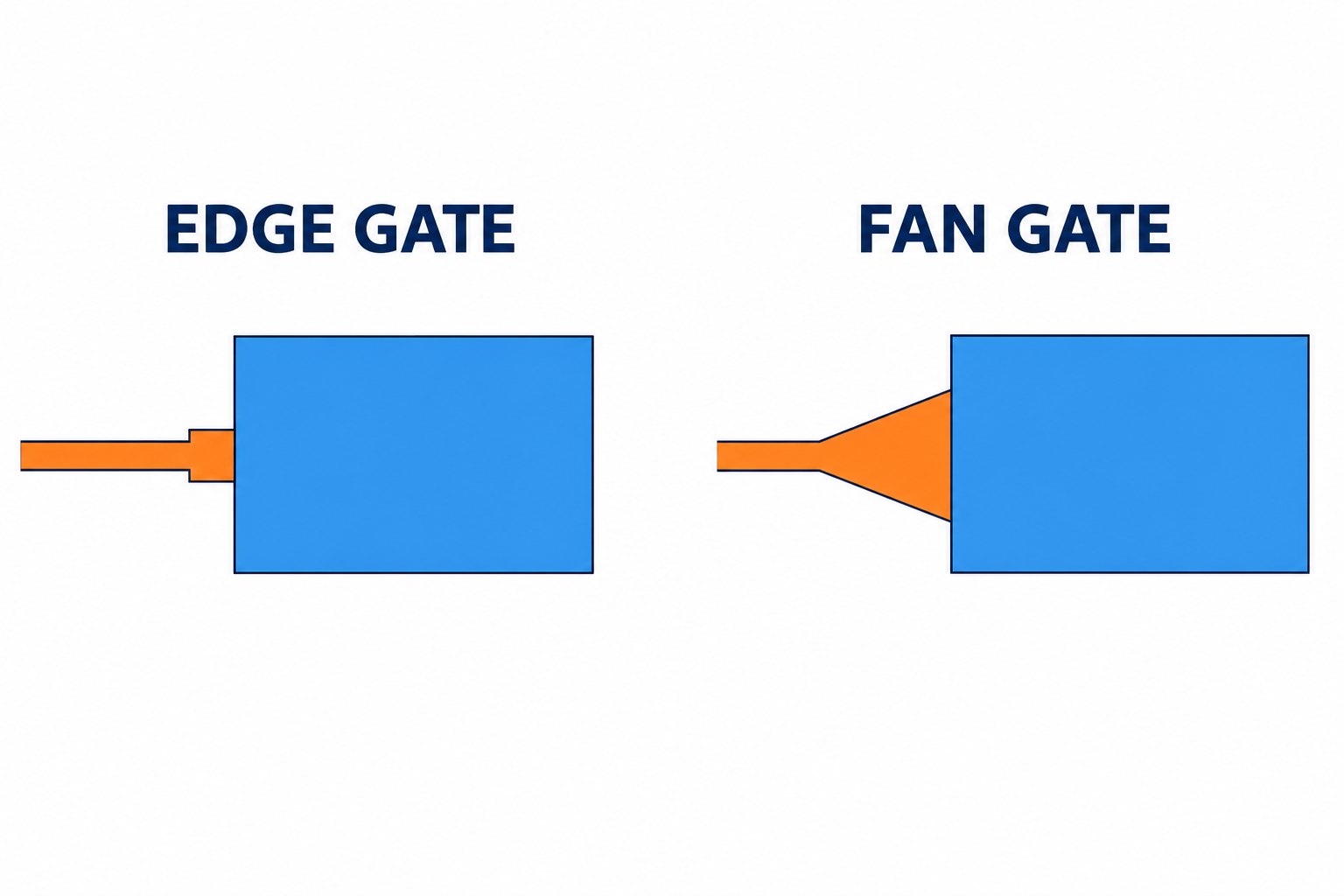
Figure 2. Edge and fan gates differ in entry width. Simplified plan views; thickness and gate land are not shown.
Tunnel, Cashew And Pinpoint Gates
These options can support automatic separation, but their mechanisms differ. Tunnel gates pass beneath the parting line. Cashew gates use a curved passage to reach another surface. Pinpoint gates commonly separate through a three-plate opening sequence.
A brittle runner may break during extraction. A tough resin may stretch or leave an unacceptable remnant. Validate separation using your actual material grade and process conditions.
DME offers distinct cashew insert geometries for different applications. Its product choices illustrate why one curved-gate layout cannot cover every part. See DME’s cashew gate insert range.
Direct Sprue And Diaphragm Gates
A direct sprue gate offers a short feeding path. Its larger attachment area may be acceptable on a concealed or subsequently machined surface.
A diaphragm gate feeds suitable cylindrical features through a circumferential connection. It can help distribute flow around the part. However, removing the diaphragm adds an operation and requires accessible geometry.
Neither option guarantees balanced cooling or dimensional accuracy. Evaluate those separately.
How Do You Choose The Gate Location?
Choose a location that supports filling and packing while protecting functional and visible surfaces. Hide the mark only after checking these requirements.
Feed Thicker Sections Without Creating A Freeze-Off Bottleneck
A useful starting point is feeding from a thicker section toward thinner regions. Feeding a thick region through an early-freezing thin section can restrict packing.
This is a starting rule, not a substitute for flow analysis. The actual wall transitions, resin, and cooling conditions matter. Autodesk’s gate-location guidance explains this packing constraint.
Protect Seals, Snap Fits And Visible Faces
Mark prohibited gate zones on the drawing. Include sealing lands, bearing surfaces, snap-fit roots, and assembly contact areas where appropriate.
For an enclosure, a concealed edge may be suitable. That same edge may become unacceptable if a gasket seals against it. Review the assembled product, not only the isolated CAD model.
Anticipate Weld Lines And Air Traps
Flow separates around holes and rejoins downstream. Multiple gates also create meeting fronts. Consider their positions relative to loads and appearance requirements.
Adding another gate can shorten flow distance. It can also introduce another weld line. Ask the toolmaker to compare these consequences rather than simply increasing gate count.
Consider Fibre Orientation
For reinforced resins, changing the entry location changes the flow pattern and can alter fibre orientation. This affects directional properties and distortion.
Material-specific guidance is essential. Solvay’s Ixef PARA tooling guide discusses gate placement and flow behaviour for that material family. Do not transfer its numerical recommendations to unrelated resins.
How Large Should The Gate Be?
There is no universal gate diameter or wall-thickness percentage for every injection moulded part. Size the gate for the actual resin, geometry, and packing requirement.
For a rectangular gate, assess width, thickness, and land length. The land is the short restricted passage immediately before the cavity. For a round gate, diameter and passage geometry matter.
An undersized gate can create excessive pressure loss and shear. It may also freeze before adequate packing. An oversized gate can complicate separation and increase the vestige.
Use the resin supplier’s processing guide as the starting reference. Then evaluate:
- Flow length and the thinnest sections along the filling path.
- Resin viscosity, reinforcement, and sensitivity to shear or heat.
- Required packing time and local cooling.
- Available machine pressure and the permitted process window.
- Gate removal, surface damage, and vestige limits.
Ask for a proposed gate section and a validation method. A quoted diameter without material and geometry context is incomplete.
Should You Choose A Cold Runner Or Hot Runner?
Choose the runner system using total production cost and process requirements. Gate appearance alone does not decide the answer.
A cold runner solidifies with the shot and requires separation. You must account for handling and permitted runner reuse. Regrind suitability depends on the material and customer specification.
A hot runner keeps material molten within the feeding system. It can reduce cold-runner waste, but adds heating and maintenance requirements. It does not eliminate startup scrap or every source of material loss.
Thermal gates rely on thermal behaviour at the gate. Valve gates use a moving pin to control opening and closure. Husky supplies both configurations; see its hot-runner systems overview.
A valve gate can leave a visible witness mark. Approve its appearance on samples rather than assuming a perfectly unmarked surface.
For quotations, compare tooling investment, runner material, cycle time, trimming labour, maintenance, and expected scrap. Use your annual quantity and programme life. Avoid selecting solely by the initial mould price.
Which Defects Can Be Related To The Gate?
Gate design can contribute to defects, but the defect alone does not establish the cause. Check material preparation, venting, cooling, and processing too.
| Observation | Gate-Related Possibility | Useful Next Check |
| Incomplete filling | Excessive restriction or an unsuitable flow path | Compare fill pattern, pressure demand, venting, and melt conditions |
| Sink near a thick feature | Packing path freezes too early | Review wall transitions, packing response, and local cooling |
| Jetting near entry | Melt enters open space as a narrow stream | Examine entry direction, gate geometry, and initial fill speed |
| Whitening at separation | Stress during trimming or automatic break-off | Inspect separation motion, resin behaviour, and remaining vestige |
| Weak weld region | Flow fronts meet in a critical location | Review meeting-front conditions and test functional strength |
| Warpage | Flow and packing imbalance contribute to distortion | Compare cavity filling, cooling, orientation, and dimensional results |
Treat this table as an investigation checklist. Do not enlarge or relocate a gate before confirming the underlying mechanism.
How Should You Validate The Gate Before Production?
Approve the gate through a documented mould trial using the intended resin and representative production conditions.
Simulation helps compare candidate locations before cutting steel. Autodesk describes gate-location analysis as preliminary input for a fuller Fill+Pack analysis. See its Moldflow gate-location tutorial.
Simulation results remain dependent on input quality. Trials must confirm the proposed process and finished-part requirements.
Check Filling And Packing
Use a controlled short-shot study, where appropriate, to observe how the cavity fills. Identify hesitation, unbalanced cavities, and unexpected meeting fronts.
For conventional freeze-off gating, a hold-time study can help identify when additional holding stops increasing part weight. Keep other settings stable. Confirm dimensions and appearance alongside weight.
Valve-gated systems require evaluation of valve timing and pressure history. Do not interpret valve closure as the same mechanism as thermal freeze-off.
Measure The Finished Gate Area
Specify the maximum projection or recess, permitted location, and relevant cosmetic criteria. Include the measurement method when acceptance could be ambiguous.
Check for cracks, sharp remnants, whitening, and interference with assembly. For critical components, include functional testing and agreed sampling across cavities.
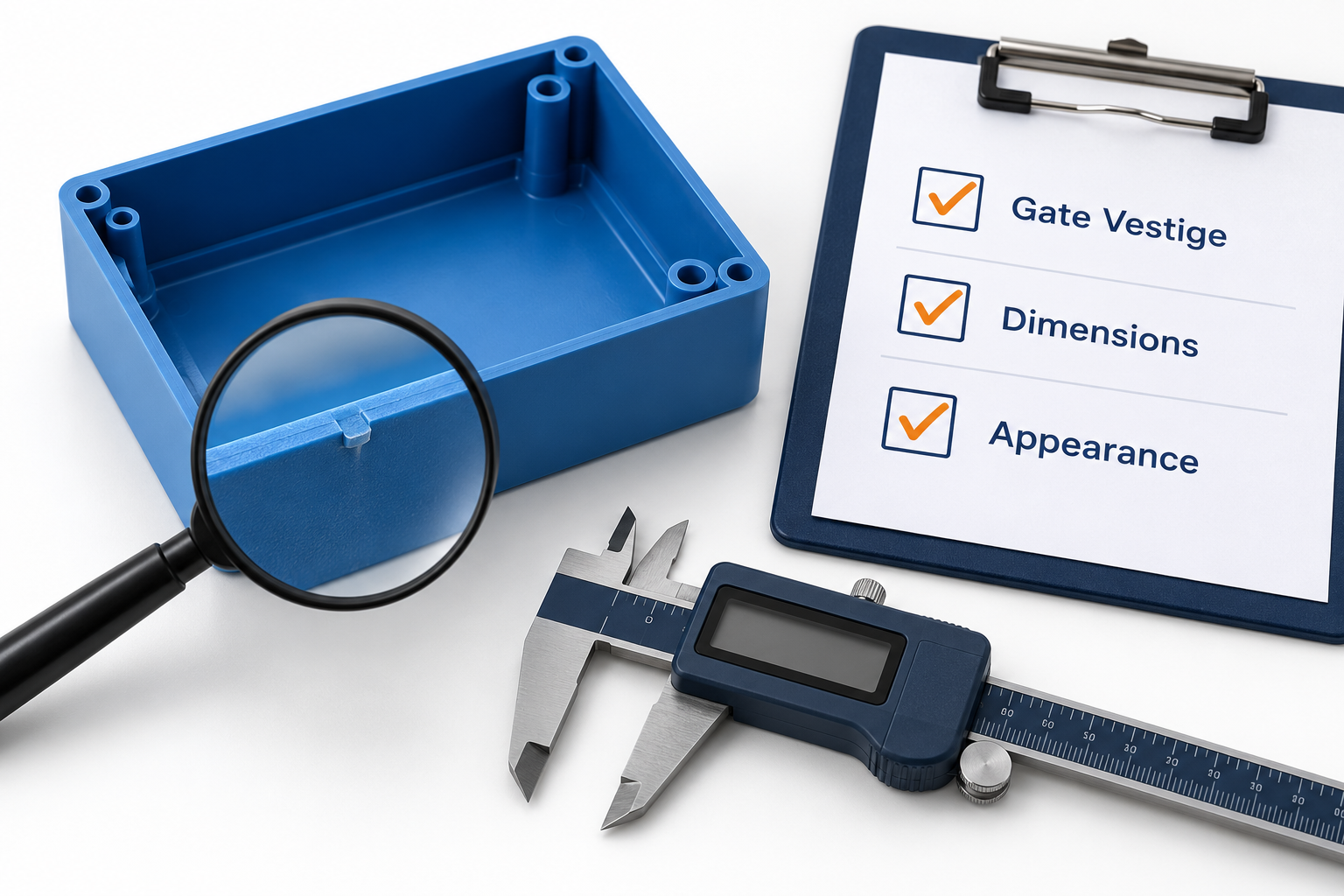
Figure 3. Define gate-vestige, dimensional, and appearance acceptance criteria. Conceptual illustration.
Record A Repeatable Approval
Retain approved samples and record the resin grade, gate configuration, and process settings. Identify each cavity where applicable.
A visually acceptable first shot does not establish production consistency. Review samples from a stable run and investigate changes after gate maintenance.
What Should You Send With A Gate-Design Enquiry?
Provide enough information to evaluate the entry location and its commercial consequences. A photograph alone rarely defines the acceptance requirements.
Include your 3D CAD, dimensioned drawing, resin grade, annual volume, and expected programme life. Mark cosmetic faces, gate exclusion zones, critical dimensions, and required surface finish.
Also explain assembly loads, sealing requirements, permitted vestige, and any restrictions on regrind. Request the proposed gate type, position, separation method, and trial approval plan.
TOPS lists plastic injection moulding services. Confirm the tooling arrangement and project-specific requirements during quotation.
Send TOPS Your Drawings For A Project Review with your CAD, resin, annual quantity, programme life, critical dimensions, and finish requirements.
Frequently Asked Questions
These answers address the decisions buyers most often need to clarify before approving a gate layout.
What Is The Difference Between A Gate And A Runner?
A runner distributes molten plastic toward cavities. A gate is the entry opening into a cavity. Direct sprue and hot-runner arrangements modify the feeding path, but the entry still needs deliberate design.
Which Injection Moulding Gate Is Best?
There is no single best type. An edge gate may suit accessible trimming. A tunnel gate may support automatic separation. A valve gate may justify its complexity when controlled closure is valuable.
Can A Gate Leave No Visible Mark?
Do not assume that it can. You can often place the vestige on a concealed surface or reduce its prominence. Agree on acceptable samples and measurable limits before production.
Is A Pinpoint Gate The Same As A Valve Gate?
No. A conventional pinpoint gate is a small opening commonly used with three-plate tooling. A valve gate uses a movable pin within a hot-runner system.
Does A Larger Gate Always Improve The Part?
No. It can reduce restriction or improve packing access, but may worsen removal and appearance. Evaluate the complete process rather than maximising gate size.
Can You Change The Gate After The Mould Is Built?
Sometimes. Feasibility depends on inserts, steel condition, cooling, and available space. Relocation can require substantial rework and another trial. Review alternative locations before tooling approval.
Conclusion
Select your gate around filling, packing, function, and acceptable vestige. Compare tooling and recurring costs together. Then validate the proposed layout with your actual resin and finished-part requirements. A documented gate approval gives you a clearer basis for consistent production and supplier acceptance.


