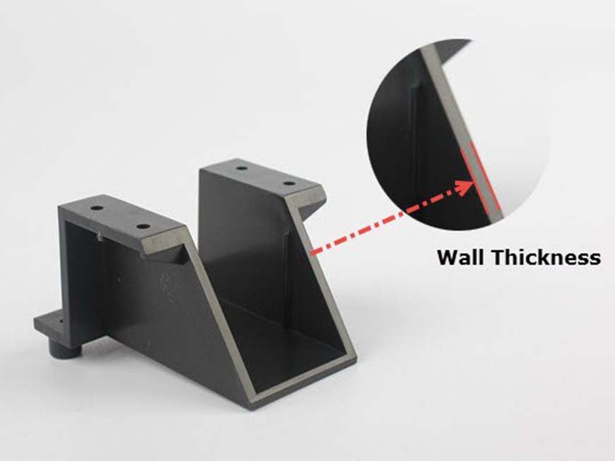
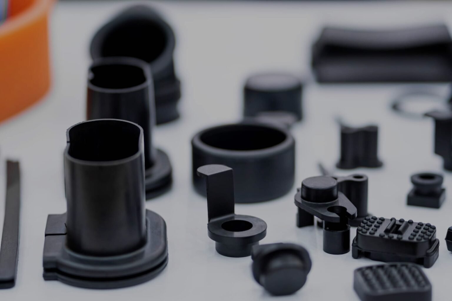
When you examine everyday molded items—such as a plastic gas can, a toothbrush holder, or a silverware tray—you’ll notice that their walls are relatively uniform. This design consistency is no accident; maintaining proper wall thickness is one of the most essential principles in plastic injection molding. Uniform walls promote smooth resin flow, predictable cooling, and dimensional stability. On the other hand, uneven wall thickness can cause sink marks, warping, voids, or even part failure.
This article explores the key principles behind injection molding wall thickness, covering recommended ranges, material considerations, geometric adjustments, and manufacturability tips to help engineers design reliable, high-quality plastic components.
Importance of Uniform Wall Thickness
Importance of Uniform Wall Thickness
Uniform wall thickness ensures even cooling and consistent material shrinkage during the injection molding process. If some areas cool faster than others, internal stresses build up—leading to warp, distortion, or cosmetic defects.
A few key rules form the foundation of good wall design:
Consistency: Walls should remain as uniform as possible throughout the part.
Ratio rule: A wall section should be no thinner than 40–60% of adjacent walls.
Avoid abrupt transitions: Gradually taper thick sections into thin ones to maintain flow balance.
Minimize internal stress: Use smooth corners and rounded fillets to distribute stress evenly.
Designers must remember that functional and aesthetic requirements often conflict with these principles, so balancing geometry with manufacturability is critical.
Recommended Wall Thickness in Injection Molding Design
Recommended Wall Thickness in Injection Molding Design
Proper wall thickness reduces material waste, ensures stable filling, and prevents defects like sink marks or short shots. While exact dimensions depend on the polymer used, several general rules apply:
Avoid long, unsupported spans: Large flat surfaces are prone to sink and deformation. Reinforce them with ribs or curvature.
Use ribs for stiffness: Instead of thick walls, add ribs—thin protrusions that provide strength without excessive material.
Add radii to internal corners: A radius equal to at least 25% of wall thickness strengthens corners and reduces stress concentration.
Maintain consistent draft angles: Apply around 1° per inch (25 mm) of cavity depth to facilitate part ejection.
Design bosses properly: Boss walls should be 40–60% the thickness of the surrounding material to prevent sink marks.
These rules create parts that are easier to mold, require fewer design iterations, and perform better in end-use environments.
Choosing Materials with Wall Thickness in Mind
Choosing Materials with Wall Thickness in Mind
Material selection plays a central role in determining wall thickness. Every resin flows, cools, and shrinks differently. Designers must weigh factors such as:
Mechanical strength and flexibility
Resistance to heat, chemicals, or UV exposure
Flame resistance and temperature limits
Optical properties (clarity, color, opacity)
Electrical insulation or EMI resistance
Selecting materials compatible with the intended wall thickness ensures better molding outcomes and reduces the risk of warping or cracking.
Typical Recommended Wall Thickness by Material
| Material | Recommended Wall Thickness (inches) |
| ABS | 0.045 – 0.140 |
| Acetal (POM) | 0.030 – 0.120 |
| Acrylic | 0.025 – 0.500 |
| Liquid Crystal Polymer (LCP) | 0.030 – 0.120 |
| Long-Fiber Reinforced Plastics | 0.075 – 1.000 |
| Nylon (PA) | 0.030 – 0.115 |
| Polycarbonate (PC) | 0.040 – 0.150 |
| Polyester (PET, PBT) | 0.025 – 0.125 |
| Polyethylene (PE) | 0.030 – 0.200 |
| Polyphenylene Sulfide (PPS) | 0.020 – 0.180 |
| Polypropylene (PP) | 0.025 – 0.150 |
| Polystyrene (PS) | 0.035 – 0.150 |
| Polyurethane (PU) | 0.080 – 0.750 |
These ranges serve as starting points—factors like mold design, gating, and filler content can shift the ideal wall dimensions.
Material Behavior and Additives
Different materials behave differently during the molding cycle:
Nylon 6/6: Offers good flow and impact resistance for thin walls but may warp under heat. Adding glass fiber reinforcement enhances both strength and thermal resistance.
Polycarbonate vs. Acrylic: Polycarbonate is robust and used in optical applications, yet acrylic performs better in thicker sections with fewer voids and bubbles.
Liquid Silicone Rubber (LSR): Exceptional for optical and medical components, allowing thicker or uneven walls without significant warpage.
K-Resin (SBC): A strong alternative to ABS for transparent parts requiring impact resistance.
Liquid Crystal Polymer (LCP): Enables ultra-thin sections with high strength and rigidity.
Additives like glass, talc, or carbon fibers can significantly alter flow, shrinkage, and heat distribution. These should be considered during material selection and tool design.
Geometry Tweaks to Strengthen Walls
Even when ideal wall thickness can’t be maintained, designers can apply clever geometric modifications to maintain part integrity:
Coring: Removing material from thick areas (similar to hollowing out a solid mass) prevents sink marks, reduces weight, and improves cooling uniformity.
Gussets: Adding gussets strengthens tall, thin walls or flange sections without increasing wall thickness.
Fillets and transitions: Use smooth transitions to reduce internal stress and avoid uneven cooling.
Avoid shadowing: Design geometry so that all areas cool evenly; uneven cooling creates visual and structural defects.
These techniques can dramatically improve moldability and reduce manufacturing costs.
Design for Manufacturability (DFM) Feedback
Before tooling begins, always review the Design for Manufacturability (DFM) report provided by your injection molding partner. DFM analysis helps identify issues before production, including:
Wall thickness variations: Color-coded maps highlight overly thick or thin areas.
Draft angle issues: Recommendations ensure parts eject smoothly without damage.
Gate and ejector locations: Proper placement minimizes cosmetic marks and stress points.
Parting lines and undercuts: Identifies features requiring side actions or inserts.
Flow simulation results: Pressure distribution, potential knit lines, and cooling balance.
This proactive approach ensures cost-effective mold design, reduces rework, and improves part quality.
Summary
Maintaining consistent wall thickness in injection molding is a cornerstone of quality plastic part design. It affects everything—from resin flow and cooling to cosmetic appearance and dimensional accuracy. By combining sound geometric principles, proper material selection, and DFM analysis, designers can minimize defects, enhance strength, and achieve repeatable manufacturing results.
Uniform wall thickness isn’t just a guideline—it’s a design philosophy that drives efficiency and quality in every molded part.
FAQ
- Why is uniform wall thickness important in injection molding?
It ensures even cooling and shrinkage, preventing defects like warp, sink marks, and voids. - What happens if the wall thickness varies too much?
Uneven thickness causes differential cooling, leading to stress, deformation, and dimensional inaccuracies. - How do I determine the best wall thickness for my part?
Consult the material’s recommended range and use simulation tools or DFM analysis to validate the design. - Can fillers like glass fiber help with wall stability?
Yes, fillers improve strength and reduce sink but may increase warping in thin areas due to uneven flow. - What is the purpose of coring in thick parts?
Coring removes excess material in thick regions, improving cooling, reducing weight, and avoiding sink marks. - How do draft angles relate to wall thickness?
A consistent draft (around 1° per inch of depth) helps the part release smoothly without damaging walls. - What materials are best for thin-walled injection molding?
Materials like Nylon 6/6, Polycarbonate, and Liquid Crystal Polymer (LCP)are excellent for thin-wall designs due to superior flow properties.
![]()