For product designers and manufacturing engineers, the bridge between a CAD model and a physical plastic part is built on efficiency. One of the most critical decisions in this process—often overlooked until the quoting stage—is determining the correct Injection Press Size.
Selecting the wrong machine size is not just a logistical error; it is a costly one. A machine that is too small leads to defective parts (flash, short shots), while a machine that is too large wastes energy, increases cycle times, and can even degrade the plastic material.
Contrary to popular belief, “bigger is better” is rarely true in injection molding. This guide expands on the core principles of press sizing to help you optimize your designs for production.
The Core Physics: The Battle of Forces
To understand press sizing, you must understand what happens inside the mold. During injection, molten plastic is shot into the cavity at incredibly high pressures (often ranging from 3,000 to 20,000+ psi).
This internal pressure acts like a hydraulic jack, trying to force the two halves of the mold apart. The injection molding machine’s Clamping Unit must provide enough opposing force to keep the mold shut.
The fundamental equation governing this is:
$$\text{Injection Pressure} \times \text{Projected Area} = \text{Required Clamping Force}$$
Here are the three critical steps to calculating this correctly.
1. Physical Constraints: Understanding Tonnage and Dimensions
Before calculating force, you must ensure the mold physically fits the machine. This is a “Goldilocks” scenario—the fit must be just right.
The Dangers of “Too Big”
It might seem safe to put a small mold in a massive 400-ton press, but this often causes failure:
Minimum Shut Height: Large presses have a limit on how tightly they can close. If your mold is too thin, the press cannot clamp it at all.
Platen Deflection: If a small mold is centered on a massive platen, the clamping force may bend the platen edges around the mold, leading to damage and flash.
The Dangers of “Too Small”
Tie Bar Spacing: Presses have four large pillars (tie bars) that guide the platens. If your mold base is wide, it may not fit between these bars, even if the tonnage calculation is correct.
Daylight Opening: If the product is deep (e.g., a trash can), the machine must open wide enough to eject the part. Smaller presses have limited opening strokes.
Key Takeaway: Always verify the Tie Bar Spacing and Min/Max Mold Height specs of your molder’s equipment early in the design phase.
2. The Geometry: Projected Area and Shot Volume
Calculating Projected Shut-off Area
The most important variable in tonnage calculation is the Projected Shut-off Area. Imagine shining a light directly perpendicular to the mold’s parting line; the “shadow” cast by the part is the projected area.
Holes and Windows: Do not subtract holes within the part design from this area calculation unless the mold creates a mechanical shut-off there. The plastic pressure still acts on the sliding cores.
The Rule of Thumb: Generally, industry standards dictate 2 to 5 tons of clamp force per square inch of projected area.
Standard parts: ~2.5 tons/sq. in.
Thin-walled/High-viscosity parts: 3–5 tons/sq. in.
Note: Wall thickness does not directly increase clamp tonnage requirements, but it does dictate cooling time and injection pressure.
Calculating Shot Volume (Barrel Capacity)
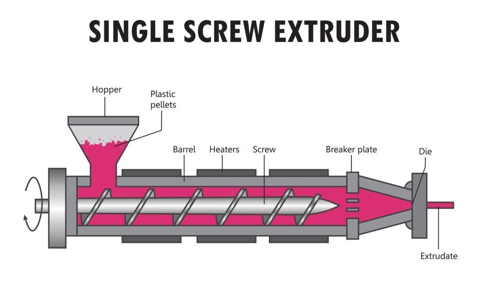
You must also match the volume of plastic in your part (plus the runner system) to the machine’s barrel size.
The Degradation Risk: If you shoot a tiny part using a massive barrel, the plastic resin sits in the heated barrel for multiple cycles before being used. This extended “residence time” cooks the polymer, causing degradation, discoloration, and brittleness.
The Solution: Utilize Mold Flow Analysis. This software simulation predicts the exact volume of the part and runner, ensuring you select a machine where the shot size utilizes roughly 20%–80% of the barrel’s capacity.
3. The Calculation: Clamping Force and Safety Factors
Once you have your dimensions, you must calculate the specific force required to keep the mold closed. This is influenced heavily by the material’s viscosity.
The MFI Factor
The Melt Flow Index (MFI) measures how easily a polymer flows.
High MFI (Low Viscosity): Flows easily (like water). While easier to fill, these materials can easily seep into microscopic gaps in the mold, causing “flash” (excess plastic). This often requires higher clamping precision and force to seal the mold tight.
Low MFI (High Viscosity): Stiff flow (like molasses). These require high injection pressures to push the material into the cavity, which in turn pushes back harder against the clamp.
The Calculation Formula
To ensure a robust process window, engineers apply a “Safety Factor” to the base calculation.
Step 1: Determine Base Tonnage
Multiply the Projected Area by the Tonnage Factor (usually 2.5 tons/in² for standard resins).
$$\text{Base Tonnage} = \text{Projected Area (in}^2\text{)} \times 2.5$$
Step 2: Add Safety Factor
Add a buffer (typically 10%) to account for process variations, material inconsistencies, or pressure spikes.
$$\text{Final Tonnage} = \text{Base Tonnage} + 10\%$$
Practical Example
Let’s calculate the press size for a rectangular plastic housing.
Part Dimensions: 10 inches x 12 inches.
Projected Area: 120 square inches.
Base Calculation: $120 \text{ sq. in.} \times 2.5 \text{ tons/sq. in.} = 300 \text{ tons}$.
Safety Buffer: $300 \text{ tons} \times 0.10 = 30 \text{ tons}$.
Total Required: $300 + 30 = \mathbf{330 \text{ tons}}$.
In this scenario, a 300-ton press would be running at maximum capacity (risky), while a 400-ton press would offer a comfortable operating window.
Summary
Determining press size is a blend of geometry, physics, and material science. By calculating the Projected Area, understanding the Physical Constraints of the machine (tie bars/barrel size), and applying the correct Safety Factors, you can ensure your product is manufactured efficiently.
Pro Tip: Do not attempt these calculations in a vacuum. Partner with your injection molder early. They can run Mold Flow Analysis to validate your calculations and suggest minor design tweaks—such as reducing projected area or optimizing wall thickness—that could allow you to use a smaller, less expensive machine.
FAQs
Q1: What is the difference between Projected Area and Total Surface Area?
A: This is the most crucial distinction in the calculation.
Total Surface Area is the sum of all external surfaces of the part (primarily used to calculate material usage and cooling needs).
Projected Area is only the area seen when looking perpendicular to the mold’s parting line (i.e., in the direction of the clamping force). Only this area directly bears the internal plastic pressure, making it the sole geometric parameter needed for calculating clamp force. For instance, the sides of a deep bucket are not included in the projected area for tonnage calculation.
Q2: Why do I need to add a 10% “Safety Factor” to my calculation?
A: The Safety Factor is essential for providing a stable Process Window. In real-world production, there are many uncontrollable variables:
Material Batch Variation: Viscosity (MFI) can vary slightly between different batches of the same resin.
Process Fluctuation: Minor changes in machine temperature, fill speed, or environmental humidity.
Pressure Spikes: The final stages of mold filling can generate brief, high-pressure peaks. Adding a 10% buffer ensures the machine can reliably maintain mold closure when these inevitable variations occur, thus minimizing defects like flash.
Q3: What are the consequences if I choose a press tonnage below the required amount?
A: Undersized tonnage is one of the most common causes of defects, leading to two main problems:
Flash: This is the direct result. When clamping force is insufficient to resist injection pressure, the mold opens slightly at the parting line, causing molten plastic to leak out and form a thin layer of excess material that requires costly secondary processing.
Short Shots (Underfilling): To prevent flash, operators might reduce the injection pressure. If the pressure is dropped too low, the plastic may fail to fully fill all corners of the mold cavity, resulting in an incomplete or flawed part. A tonnage-deficient machine will therefore struggle to produce consistent, high-quality parts.


