


CNC inspection temperature can change whether a measured feature appears to meet its drawing tolerance. Agree the reference temperature, part stabilization, correction method, and reporting conditions before ordering. A room thermometer alone does not establish the workpiece temperature or the reliability of the result.
Distinguish Reference Temperature From Measurement Temperature
The reference temperature defines the specified geometry; the measurement temperature describes the conditions when you inspect the part.
ISO 1:2022 defines reference-temperature concepts for geometrical and dimensional properties. These include size, location, orientation, form, and surface texture.
The standard reference temperature is 20 °C. NIST's dimensional metrology guidance explains why dimensions need a common temperature basis. It also explains measurement away from that temperature with appropriate thermal correction and uncertainty evaluation.
That distinction matters when comparing supplier and receiving reports. A measurement taken in a warmer room is not automatically invalid. However, you need evidence that the result represents the specified reference condition with suitable uncertainty.
Avoid specifying “20 °C inspection” without explaining what you mean. State the drawing reference condition separately from the permitted measurement environment and reporting method.
Identify When Temperature Can Affect Your Acceptance Decision
Temperature deserves explicit review when its dimensional effect could influence the tolerance decision.
Focus on the features that drive assembly or function. Examples include bearing seats, long hole patterns, precision shafts, and mating components with different materials.
The relevant question is not whether a dimension changes at all. Ask whether the estimated effect and its uncertainty matter against your acceptance requirements.
| Part Or Feature | Temperature Question | Buyer Action |
|---|---|---|
| Precision shaft diameter | Was the shaft stable when measured? | Define stabilization and reporting conditions |
| Long plate hole pattern | Could temperature differences affect distances? | Review measurement length and temperature distribution |
| Dissimilar mating materials | Do both reports use a common reference basis? | Separate manufacturing acceptance from service-temperature fit |
| Part measured after machining | Could recent processing leave a temperature difference? | Establish a suitable inspection release condition |
| Feature near a tolerance boundary | Could measurement uncertainty change the decision? | Agree the conformity decision rule |
Do not impose identical controls on every dimension without review. Start with critical features and the required measurement capability. Our CNC machining tolerances guide provides the wider drawing context.
Review The Room Part And Measurement System Separately
Reliable temperature control considers the workpiece and measurement system, rather than only the room setting.
A part can enter a controlled room before reaching a stable temperature. Its recent machining, washing, transport, or handling history may matter. Your inspection plan should address that history where it affects results.
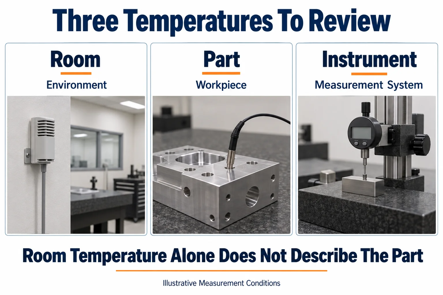
For compensated CMM measurements, Renishaw's temperature compensation guidance distinguishes axis sensors from workpiece sensors. It describes contact with the workpiece and sensor placement near the measurement region. Follow the applicable instrument instructions when designing your procedure.
Ask the supplier which temperature is recorded. An air-temperature entry does not prove that the part was at that temperature. A single workpiece reading also needs justification for a large part with possible gradients.
You should also review handling and fixture conditions. Temperature is one contributor to measurement reliability. Probe access, clamping, alignment, and calibration still require their own controls.
Establish Stabilization Criteria Instead Of Copying A Waiting Time
A useful stabilization procedure establishes a justified measurement condition for your part and method.
Do not copy a universal one-hour or overnight rule into every purchase order. Suitable conditioning depends on material, geometry, mass, previous temperature, environment, and the measurement requirement.
Ask the supplier to demonstrate a practical release criterion for representative parts. The evidence might include repeated temperature observations and measurement stability under a documented procedure.
Agree sensor locations, observation intervals, and acceptable variation where these are needed. Let the responsible metrology team justify those details. A calendar delay alone does not prove that every relevant region is stable.
For large components, ask how temperature differences across the workpiece are assessed. If significant gradients remain, a uniform expansion correction may not adequately represent the geometry.
Keep the procedure revision with the inspection record. When the part geometry or incoming condition changes, review whether the established method still applies.
Treat Thermal Compensation As A Measurement Method
Thermal compensation needs justified inputs and an uncertainty assessment before you rely on corrected dimensions.
Confirm the material identification and the coefficient of thermal expansion used. Ask where that coefficient came from and whether it suits the actual material and temperature range.
NIST's study of measurements at nonstandard temperatures examines uncertainty from temperature and expansion coefficients. A corrected number therefore does not eliminate all thermal uncertainty.
Ask how the instrument accounts for its own thermal behavior. Workpiece correction and measurement-system compensation are related, but they are not interchangeable.
Do not apply a second correction to a result already reported at the reference temperature. Request a clear statement distinguishing observed readings from corrected reported values.
If suitable inputs or uncertainty evidence are unavailable, review the measurement conditions before accepting a software correction. Moving closer to the reference condition may reduce thermal contributions, but it does not remove every measurement uncertainty.
Put Inspection Conditions In The RFQ And Report
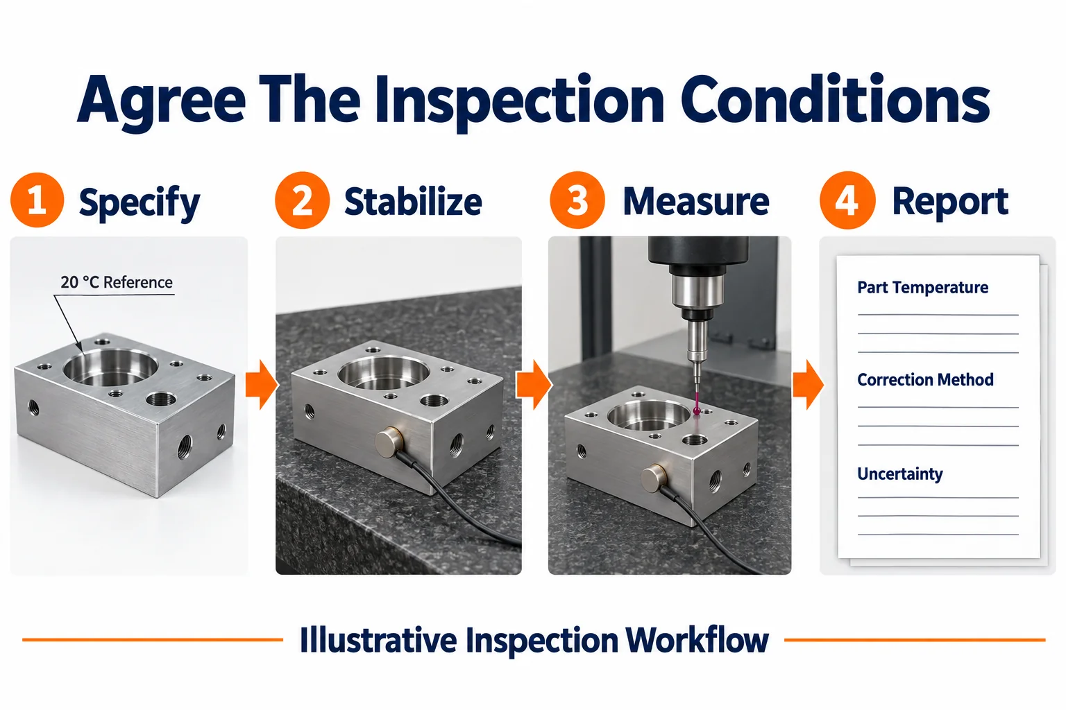
Your RFQ should make the temperature basis and acceptance evidence clear enough for both parties to reproduce the decision.
Identify critical features before requesting extensive environmental records. Then agree the controls needed for those features and the required reporting format.
| Requirement | Information To Agree |
|---|---|
| Specification basis | Drawing revision, applicable standards, and reference temperature |
| Part preparation | Processing stage, handling, and stabilization procedure |
| Temperature evidence | Relevant part and environment observations with units |
| Correction status | Whether reported dimensions are corrected, and to which reference condition |
| Method inputs | Material, expansion coefficient source, sensors, and instrument method |
| Acceptance evidence | Measurement uncertainty, decision rule, and responsible release authority |
These fields describe an inspection agreement, not a guarantee of a particular instrument capability. Ask the supplier to confirm the proposed method before purchase approval.
Special conditioning, sensor arrangements, and additional reporting can affect lead time and inspection cost. Resolve these requirements during quoting, rather than after a shipment dispute.
Resolve Conflicting Measurements Before Changing The Part
When reports disagree, compare their measurement conditions before authorizing rework or changing an offset.
First confirm that both teams measured the same feature using the same drawing revision and datum interpretation. Next compare the reference basis, actual part condition, correction status, and uncertainty.
Agree a controlled comparison using identified parts and a documented method. Preserve the original records. Avoid selecting only the reading that supports the preferred result.
If a difference remains, investigate the full measurement process. Temperature may explain part of a disagreement, but it should not become an automatic explanation for every failure.
A manufacturing tolerance and an operating-temperature requirement also serve different purposes. If service conditions determine fit, have the design authority define that requirement separately.
Frequently Asked Questions
Your inspection agreement should answer the questions that can otherwise delay incoming acceptance.
Must Every CNC Part Be Measured At Exactly 20 °C
No. The reference basis and actual measurement conditions differ. Suitability depends on the method, thermal effects, uncertainty, and agreed requirements.
Is Room Temperature Enough For A CMM Report
Not by itself when workpiece temperature affects the decision. Ask how the actual part condition and measurement-system behavior are addressed.
How Long Should A Part Stabilize Before Inspection
There is no universal duration. Establish a justified procedure for the part, incoming condition, instrument, and required measurement capability.
Does Temperature Compensation Guarantee Acceptance
No. Compensation depends on suitable inputs and a valid method. You still need the agreed uncertainty evaluation and decision rule.
Should You Change The Drawing If Receiving Measurements Differ
Compare methods and conditions first. Only an authorized engineering review should change the product specification.
Request A CNC Inspection Plan Review From TOPS
TOPS offers custom CNC machining services. Send your drawing, material, quantities, critical features, and inspection requirements. Contact us to review the manufacturing and acceptance scope before placing your order.