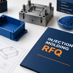



Heat set inserts for plastic parts provide metal threads installed after molding. Your approval must address the resin, insert design, boss geometry, installation method, and joint tests. A strong metal thread does not establish retention in plastic. Review the complete assembly before committing tooling or production quantities.
Confirm That Thermal Installation Fits Your Material
Your resin must support the selected thermal insertion process without unacceptable damage to the molded component.
Heat installation locally softens thermoplastic around an insert. The surrounding material flows into its external retention features. After cooling, that mechanical engagement helps resist axial extraction and rotation.
Do not apply this process automatically to thermosets, which do not remelt like thermoplastics. Identify the exact grade, reinforcement, and conditioning state. Fillers and part geometry can affect the installation window.
SPIROL compares thermal and ultrasonic installation. These are distinct processes even when an insert family supports both. Specify which method your supplier proposes rather than accepting an ambiguous “insert fitting” operation.
Select The Insert And Boss Together
Your hole and boss design should follow the selected insert manufacturer’s recommendations for the actual plastic and installation method.
Specify the insert manufacturer, series, material, thread, length, and drawing revision. Nominal screw size alone leaves the external retention design undefined. Inserts with different knurls or tapers can require different pilot holes.
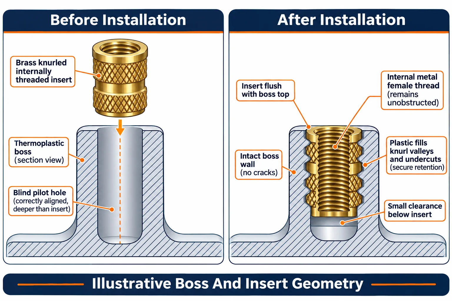
Review pilot diameter, taper, depth, boss wall, and surrounding geometry before mold release. A blind hole needs suitable clearance beneath the insert. Account for displaced plastic and the screw’s final engagement depth.
SPIROL's hole design guidance explains why these dimensions depend on the insert and plastic. Avoid copying a hole diameter from another brand’s part. Request a documented recommendation and confirm it through representative trials.
Include access for the installation tip and support tooling. A boss beside a tall wall may be reachable by a screw but inaccessible to production insertion equipment.
Define Installed Position And Assembly Load Path
Your drawing should establish the insert’s final position and how the mating assembly transfers clamp load.
Specify acceptable depth, perpendicularity, thread condition, and surrounding surface appearance. Define the reference face used for inspection. An insert that looks flush can still be tilted or poorly retained below the surface.
Review the mating clearance hole and its bearing contact. PennEngineering's insert guidance discusses supporting the mating component on the insert face to avoid jacking the insert out. Confirm the actual load path for your design.
Also check screw length. A screw that bottoms in a blind feature can create unintended loads during tightening. An insert does not automatically prevent plastic creep or loss of clamp force. Assess compression support separately where the application requires it.
Control The Installation Process Before Production
Your supplier should validate a repeatable process using representative molded parts and the specified insert.
Agree the controlled variables, including tip temperature, insertion force or movement, depth, alignment, and cooling. Do not prescribe universal settings without considering the material and equipment. Record the approved procedure and relevant inspection checks.
Support the component so insertion does not bend the housing or overload a thin boss. Check for cracking, excessive displaced plastic, damaged threads, and cosmetic distortion. Where needed, examine sectioned samples to assess plastic engagement around retention features.
Treat a changed resin, insert geometry, hole, or installation method as a review trigger. Define which changes require new trials before shipment.
Test Axial Retention And Rotation Separately
Your qualification plan should distinguish pull-out resistance, rotational retention, and actual screw assembly performance.
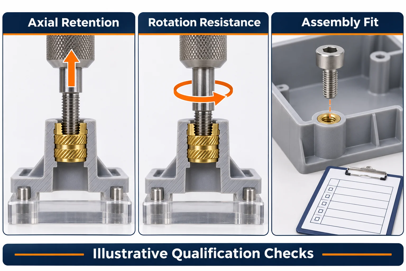
An axial test loads the insert along its axis. A rotation test assesses resistance to turning within the plastic. Neither result alone proves the complete joint suitable under service conditions.
Define sample preparation, conditioning, fixture support, loading method, and acceptance criteria before testing. A fixture supporting the boss differently from the assembly can alter the result. Record failure mode as well as the reported load or torque.
Use production-representative resin and molded geometry. Include relevant temperature, moisture, chemical exposure, and repeated assembly requirements where applicable. Avoid treating catalogue reference data as a guaranteed result for your boss.
| Approval Requirement | Define In Your RFQ | Evidence To Request |
|---|---|---|
| Material | Exact resin and conditioning | Material identity and trial conditions |
| Insert | Approved series, material, thread, geometry | Manufacturer drawing and traceability |
| Boss | Hole profile, depth, wall, access | Drawing review and representative samples |
| Installation | Method, position, controlled procedure | Setup record and inspection criteria |
| Joint Performance | Axial, rotational, assembly requirements | Defined tests and failure observations |
| Changes | Triggers requiring approval | Reviewed revision and repeat trial records |
Compare Quotes For The Complete Accepted Assembly
Your quotation comparison should include inserts, insertion tooling, handling, qualification, and recurring inspection.
A secondary insertion operation may simplify molding but adds assembly work. Production quantity, insert orientation, access, and automation options affect cost. Ask suppliers to identify included operations and evidence explicitly.
TOPS Precision provides plastic injection molding services. Submit the boss and mating assembly during feasibility review. Confirm the proposed insertion arrangements and validation scope for your specific project.
Frequently Asked Questions
Your decision should address retention in the plastic and the complete joint’s operating requirements.
Are Heat Set Inserts The Same As Molded Plastic Threads
No. Heat set inserts contain a separately manufactured metal thread and are installed after molding. Plastic threads form directly in the resin.
Can You Use Any Brass Insert With The Same Thread Size
No. External geometry and intended installation method matter. Qualify the approved insert and pilot hole as a combination.
Does Assembly Torque Replace Retention Testing
No. Successful tightening alone does not establish axial retention or resistance under your service conditions. Define the required tests separately.
Request A Threaded Boss Review
Contact us with your CAD, resin grade, insert drawing, mating screw details, and acceptance requirements. Include annual volume and program life. Agree the boss design and qualification plan before approving tooling.