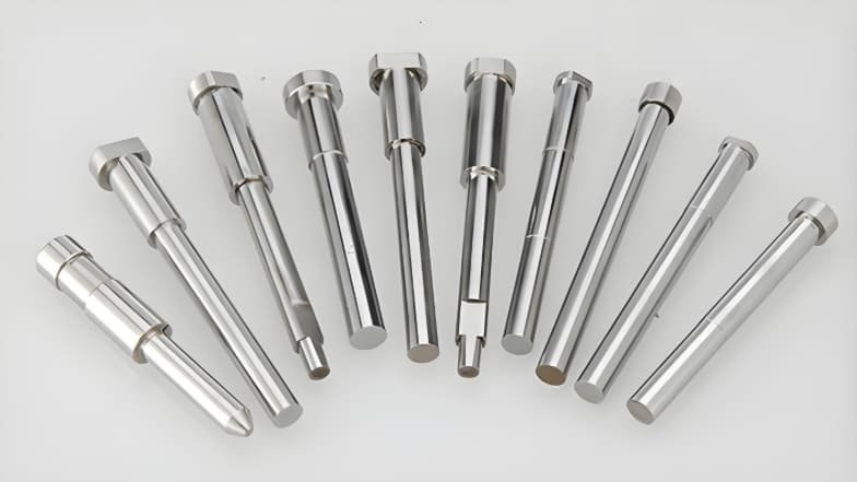
What Are Ejector Pins in Injection Molding?
In the injection molding process, ejector pins are precision components used to push molded plastic parts out of the mold cavity after they have cooled and solidified. They are part of the ejector system, a crucial mechanism that enables automated part removal, ensuring a smooth, continuous production cycle.
An injection mold typically consists of two halves:
Side A (Cavity Side): stationary side attached to the injection unit.
Side B (Core Side): movable side containing the ejector system.
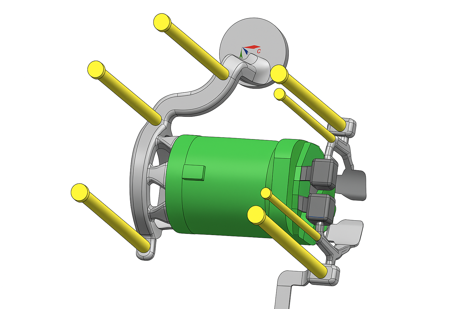
After the molten polymer is injected and cooled, the mold opens. The ejector system—driven by hydraulic or mechanical actuation—pushes the finished part out of the cavity using several ejector pins strategically placed within the mold.
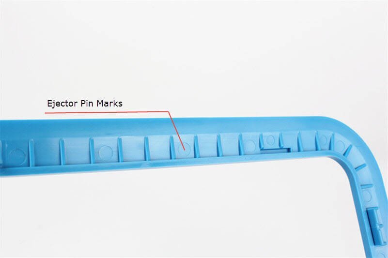
Without these pins, molded parts would adhere tightly to the mold surface, causing deformation, scratches, or cycle delays. However, since the pins apply physical force on the part, they can sometimes leave small circular impressions known as ejector pin marks. Proper pin design and placement are therefore critical to achieving defect-free parts.
Common Materials Used for Ejector Pins in Molds
Ejector pins might look simple, but the material they’re made from really matters. Since they constantly push parts out of molds under heat and pressure, they need to be strong, wear-resistant, and able to handle repeated use without bending or breaking. Let’s look at some of the most common materials used to make them and what makes each one special.
- SKD61 (H13) – The All-Rounder
This is probably the most popular choice. SKD61, also known as H13 tool steel, is a tough material that can handle both high temperatures and mechanical stress. It doesn’t wear out easily, making it great for molds used in plastic injection or die casting. You can think of it as a reliable all-purpose material for most production needs. - SKH51 – For High-Speed and High-Wear Jobs
SKH51 is a high-speed steel that’s harder and more wear-resistant than SKD61. It’s perfect for molds that run continuously or use tough materials that cause more friction. Because of its excellent hardness, it lasts longer but can be a bit more expensive. - Stainless Steel – For Corrosion Resistance
If the mold works in a humid environment or deals with corrosive plastics, stainless steel ejector pins are a good choice. They don’t rust easily and need less maintenance. However, they’re usually softer than tool steels, so they might wear faster under high pressure. - Carbide – The Tough Guy
Tungsten carbide pins are extremely hard and wear-resistant. They’re used in high-volume or abrasive molding operations where regular steel pins would wear out too quickly. On the downside, carbide is brittle, so it can chip if not handled properly. - Beryllium Copper – For Better Heat Conductivity
Sometimes, ejector pins made from beryllium copper are used in areas where heat removal is important. This material conducts heat very well, helping parts cool faster and improving cycle time. But since it’s softer, it’s usually used as inserts or combined with harder steel pins.
Types of Ejector Pins Used in Injection Molding
Types of Ejector Pins Used in Injection Molding
There are multiple types of ejector pins, each designed for specific materials, temperature conditions, and part geometries. Selecting the right pin type helps maintain dimensional accuracy and surface quality.
1. Through-Hard Ejector Pins
These pins are heat-treated throughout their entire cross-section, providing consistent hardness and strength. They are ideal for molds that operate below 200 °C. Their durability makes them suitable for most standard thermoplastic molding applications, where they resist bending and galling during repeated ejection cycles.
Advantages:
Uniform hardness throughout.
Cost-effective and easy to machine.
Good wear resistance for general plastics.
Limitations:
Limited temperature tolerance.
Can become brittle if over-hardened.
2. Nitride H13 Ejector Pins
H13 tool steel pins undergo a nitriding surface-hardening treatment, giving them a hard outer case with a tough, ductile core. They can operate up to 600 °C, making them ideal for engineering resins and semi-crystalline plastics.
Advantages:
High temperature and corrosion resistance.
Maintain tight tolerances and dimensional stability.
Limitations:
The outer nitride layer can chip if improperly aligned.
More expensive than through-hard pins.
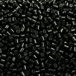
3. Black Ejector Pins
Black ejector pins are the advanced evolution of nitride H13 pins. They are coated with a self-lubricating, high-temperature surface treatment, capable of withstanding up to 1000 °C. This makes them perfect for automotive parts, high-temperature engineering plastics, and precision molds where surface finish is critical.
Advantages:
Excellent wear and thermal resistance.
Reduced friction and self-lubricating surface.
Long service life even under demanding cycles.
Limitations:
Higher initial cost.
May require precise mold design to utilize benefits fully.
4. Other Ejection Components
Besides standard ejector pins, other systems are also used depending on part geometry and finish requirements:
Ejector Sleeves: Hollow cylindrical pins used for ejecting round or tubular parts; provide even pressure and prevent deformation.
Ejector Plates: Support and guide the movement of pins, ensuring synchronized operation during ejection.
Ejector Blocks: Flat, lubricated blocks used to eject large or thin components while minimizing ejector marks.
How Do Ejector Pins Work?
How Do Ejector Pins Work
The operation of ejector pins is closely tied to the three main phases of the injection molding cycle:
1. Injection Phase
Molten plastic is injected into the mold cavity at high pressure. The cavity fills completely, taking the exact shape of the mold design.
2. Cooling Phase
After injection, the material cools and solidifies. Cooling time is carefully controlled to prevent warpage, shrinkage, or incomplete solidification.
3. Ejection Phase
Once the part has solidified, the mold halves separate. The ejector plate pushes the ejector pins forward through pre-machined holes in the core plate. The pins apply an even, axial force on the molded part, pushing it free from the mold cavity.
Automatic ejection systems use hydraulic or mechanical return springs to retract the pins after ejection. This automation shortens the cycle time and ensures consistent part removal without manual intervention.
Working Sequence:
Mold opens after cooling.
Ejector plate advances.
Pins extend and push the part out.
Pins retract as mold closes for the next cycle.
Causes and Solutions of Ejector Pin Marks
Causes and Solutions of Ejector Pin Marks
Although ejector pins are necessary, they can leave circular marks or slight dents known as ejector pin marks on the part surface. These marks can affect both appearance and functionality if not properly controlled.
1. Inadequate Cooling Time
Ejecting the part before it fully solidifies causes surface indentation.
Solution: Increase cooling time or optimize cooling channel design for uniform temperature distribution.
2. Thin-Walled Products
Thin walls are more prone to visible ejector marks and deformation.
Solution: Maintain a minimum wall thickness of 2.5 mm or use alternative ejection methods like ejector blades or air ejection.
3. Improper Dwell Time or Temperature
High dwell temperature or excessive dwell time can soften the material during ejection, increasing the risk of pin marks.
Solution: Optimize dwell time and maintain mold temperature below the glass transition temperature (Tg) of the polymer.
4. Poor Pin Placement
Incorrect placement can cause uneven force and visible surface damage.
Best Practices:
Place pins in thicker sections or non-aesthetic areas.
Avoid textured or sloped surfaces.
Maintain proper spacing from cooling channels to prevent hot spots.
Use more pins for complex parts to distribute force evenly.
5. Inappropriate Machine or Pressure Settings
Oversized machines may exert unnecessary clamping force, increasing stress during ejection.
Solution: Match machine tonnage to part size and adjust holding pressure for easier release.
6. Additional Preventive Measures
Use abrasion-resistant plastics such as nylon or UHMWPE.
Apply mold release agents for smoother ejection.
Design parts with draft angles (1°–3°) to facilitate part release.
How to Choose the Right Ejector Pins
Selecting the correct ejector pins depends on several design and process parameters.
1. Pin Diameter
Larger pins distribute ejection force more effectively and minimize surface indentation. Use standard diameters (avoid non-standard decimals).
2. Pin Length and Size
Pin length should match the part depth; too short may fail to eject, too long may bend. Balance diameter and length to prevent deflection under load.
3. Material Strength
Ejector pins must resist bending, wear, and fatigue. Minimum pin diameter should be ≥ 2.5 mm for adequate stiffness.
Tip: For small or slender pins, use shoulder ejector pins for extra strength.
4. Material Type
Common materials include:
H13 tool steel: heat-resistant and durable.
M2 steel: excellent hardness for precision molds.
420 stainless steel: corrosion-resistant, ideal for medical or food-grade parts.
5. Cost Considerations
High-performance pins may increase initial tooling costs but reduce downtime and maintenance. Evaluate long-term performance versus replacement frequency.
Conclusion
Ejector pins play an indispensable role in the injection molding process, ensuring smooth, automated removal of molded parts without damage. Understanding the types, working principles, and potential defects allows engineers to optimize part design, extend mold life, and maintain consistent quality.
Choosing the proper pin material, diameter, and placement can prevent surface defects and improve manufacturing efficiency. Whether for automotive, electronics, or consumer products, a well-designed ejector system is key to a reliable molding process.
FAQs
- What is an ejector pin mark?
An ejector pin mark is a small circular indentation left on a molded part when the pin pushes it out of the cavity. These marks can appear as shiny or white spots on visible surfaces. - How can I identify ejector pin marks?
They are usually found on the side opposite the gate and appear as small, round dents corresponding to the pin locations inside the mold. - What materials are used to make ejector pins?
Ejector pins are typically made from tool steels such as H13, M2, and 420 stainless steel, which can be heat-treated for high wear resistance. - How can ejector pin marks be minimized?
Optimize pin placement, adjust cooling time, add draft angles, and use polished mold surfaces or ejector blocks for high-finish parts. - What alternatives exist to ejector pins?
For delicate parts, alternatives include ejector sleeves, ejector blades, and pneumatic or air ejection systems, which reduce surface contact and minimize defects.
Read More:
Common Cosmetic Defects in Injection Molding and How to Fix Them
5 Things You Need to Know About Plastic Injection Molding
![]()