If you’ve ever examined a molded plastic part and noticed a faint line running across its surface, you’ve seen a knit line. These marks are one of the most common issues in injection molding — and while they can’t be completely eliminated, understanding how they form and how to minimize them can make a huge difference in both part quality and aesthetic appearance.
In this guide, we’ll dive into what knit lines are, what causes them, and how engineers can reduce their occurrence through careful design, material choice, and process control.
What Are Knit Lines in Injection Molding?
What Are Knit Lines in Injection Molding
A knit line (also called a weld line or meld line) occurs when two or more molten plastic flow fronts meet and fail to fully fuse together during the molding process. This typically happens when the plastic must flow around a core, boss, hole, or other obstruction before reuniting on the other side.
Imagine a river that splits around a rock and rejoins — you’ll see a ripple where the two streams meet again. Similarly, when molten plastic merges after being separated, a subtle line or seam forms because the polymer chains at the interface don’t fully interlock.
Common Locations of Knit Lines
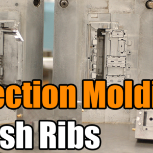
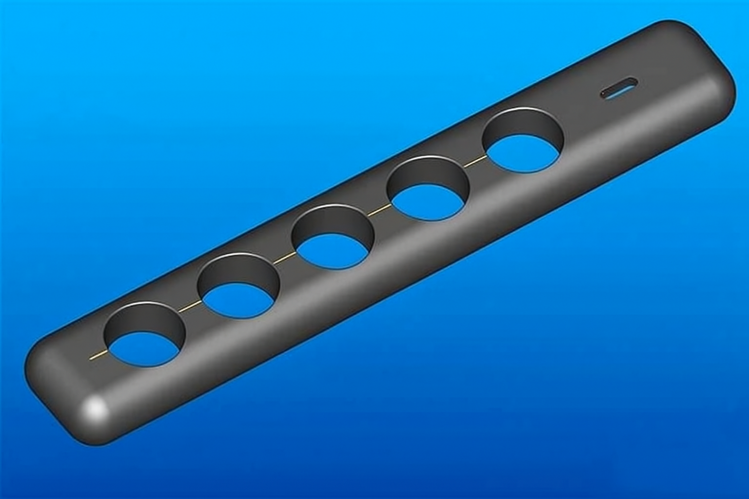
Around holes, ribs, and bosses
Near inserts or core pins
At gate junctions where multiple flow paths meet
Along thin-wall regions or sharp corners
While sometimes only cosmetic, knit lines can also indicate structural weaknesses, especially in parts subject to stress or pressure.
What Causes Knit Lines in Injection Molding?
Knit lines occur due to incomplete fusion of two plastic flow fronts. Several design and processing factors contribute to this phenomenon:
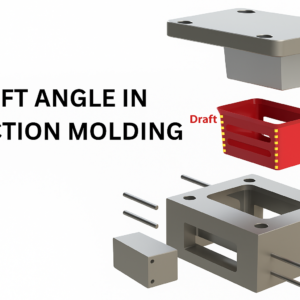
Part Design and Geometry – Features like holes, ribs, and sharp corners split the melt flow, creating multiple flow fronts that later converge.
Gate Location – Poor gate placement can cause flow fronts to meet at visible or structurally critical areas.
Material Type – Some thermoplastics have lower flowability or poorer bonding ability.
Filler Content – Materials with high glass fiber or mineral filler content tend to form weaker knit lines.
Mold Temperature and Injection Speed – Low temperature or slow fill rates can cause premature cooling, preventing proper fusion.
How to Minimize Knit Lines
Although it’s impossible to completely eliminate knit lines, you can significantly reduce their appearance and negative effects using the following methods.
1. Optimize Gate Location with Mold Flow Simulation
One of the most effective strategies is to use mold flow analysis software (such as Autodesk Moldflow or Moldex3D) during the design stage. Simulation helps predict flow patterns and identify where knit lines are likely to form.
By adjusting gate placement, you can:
Redirect flow so knit lines occur in less visible areas.
Ensure flow fronts meet in low-stress regions.
Improve packing uniformity for stronger bonds.
2. Adjust Process Parameters
Fine-tuning molding parameters can greatly improve flow fusion and surface finish.
Key adjustments include:
Increase mold and melt temperature – Ensures the plastic remains fluid longer, promoting better molecular interlocking.
Increase injection speed and pressure – Helps flow fronts meet with more energy, leading to better fusion.
Optimize holding pressure and time – Ensures proper packing and reduces surface defects.
Improve venting – Prevents trapped air from cooling the melt prematurely at the convergence point.
Even small process changes can reduce the visibility and weakness of knit lines.
3. Select the Right Material
Material choice plays a major role in how well flow fronts merge. Some plastics naturally bond better than others.
For example:
Polypropylene (PP) often forms stronger knit lines than Thermoplastic Olefin (TPO), even though PP is generally weaker overall.
Materials with high melt flow index (MFI) tend to fill cavities more smoothly, improving fusion quality.
When choosing materials, consult the supplier’s data sheets and consider the flow and bonding behavior for your specific mold design.
4. Manage Fillers and Additives
Fiber-filled plastics (such as glass-filled nylon or PBT) are particularly prone to weak knit lines. The reason: fibers don’t melt and therefore can’t fuse across the flow front.
To mitigate this:
Use short fibers or glass beads instead of long fibers to improve re-bonding.
Consider unfilled resins for aesthetic or high-strength parts where knit lines are critical.
Use impact modifiers or compatibilizers to enhance molecular bonding at weld areas.
5. Use Valve Gate Control
When multiple valve gates feed the same cavity, their opening and closing timing determines how the flow fronts meet.
Using valve gate sequencing and cavity pressure sensors, you can:
Coordinate gate operation for smooth flow merging.
Prevent visible knit lines by overlapping flow fronts more evenly.
Improve part consistency across cavities in multi-cavity molds.
Advanced systems like RJG’s CoPilot® or MeltFlipper® technologies can provide real-time feedback and optimize gate control automatically.
6. Improve Part and Mold Design
Engineering design plays a critical role in avoiding knit line issues. Consider:
Reducing sharp corners or thick-to-thin transitions that disrupt flow.
Adding flow leaders or channels to balance melt distribution.
Adjusting wall thickness to maintain consistent flow rates.
Positioning gates to ensure flow fronts merge at less visible or low-stress regions.
Design modifications early in the development stage can save significant cost and effort later.
7. Test and Inspect Knit Lines
Even with careful optimization, knit lines can still occur. Therefore, regular inspection is essential:
Visual inspection: Under good lighting to spot surface defects.
Mechanical testing: Tensile or flexural strength tests to evaluate weak points.
Microscopic examination: To analyze bonding at the molecular level.
If knit lines appear consistently in the same area, revisit mold design and processing parameters to identify the root cause.
Conclusion
Knit lines are an unavoidable reality in injection molding — they form where two molten flow fronts meet. However, with smart design, optimized processing, and careful material selection, you can drastically minimize their appearance and improve structural integrity.
By understanding how and why knit lines form, you can design parts that not only look better but also perform more reliably.
In fact, when properly managed, a meld line — where flows fully rejoin — can be nearly invisible and mechanically strong. The goal isn’t total elimination but optimization for strength, durability, and aesthetics. Contact us for more information.
FAQs
1. What is the difference between a knit line, weld line, and meld line?
These three terms are often used interchangeably, but there are subtle differences:
Knit line: Formed when two flow fronts meet at a low temperature or pressure and fail to fuse completely, leading to a visible weak line.
Weld line: Similar to a knit line but typically results from two separate flow fronts meeting head-on, often at gates or multiple injection points.
Meld line: A stronger, more uniform bond where the two flow fronts merge smoothly with good molecular interlocking.
In short, meld lines are the goal, while knit and weld lines are the defects to minimize.
2. How do knit lines affect part strength?
Knit lines create areas of poor molecular bonding, which reduces tensile and impact strength. When a part experiences stress — especially near a knit line — cracks can initiate more easily.
The degree of strength loss depends on:
The material type (amorphous vs. semi-crystalline plastics).
The temperature and pressure at the point of convergence.
The presence of fillers, such as glass fibers, that interrupt polymer flow.
Engineers often perform mechanical tests like tensile or flexural analysis to quantify the strength reduction caused by knit lines.
3. Can mold design changes eliminate knit lines completely?
No — even the most optimized mold design can’t eliminate knit lines entirely, because flow fronts must meet somewhere in any filled cavity. However, mold design can control where and how they occur.
Effective strategies include:
Positioning gates so that knit lines form in non-critical areas.
Reducing sharp edges or flow obstructions.
Designing balanced wall thickness to ensure uniform flow.
While you can’t remove knit lines completely, good mold design makes them invisible and structurally harmless.
4. Why are fiber-reinforced materials more prone to weak knit lines?
Fiber-reinforced plastics, such as glass-filled nylon (PA-GF), are more susceptible to weak knit lines because fibers don’t melt. When flow fronts meet, the thermoplastic matrix can re-fuse, but the fibers at the interface remain unbonded.
This creates microvoids and discontinuities in the knit area, reducing structural integrity. Using short fibers, glass beads, or hybrid fillers can help improve bonding strength in these regions.
5. What testing methods are used to evaluate knit lines?
Quality engineers use several methods to identify and assess knit lines:
Visual inspection: Using magnification or special lighting to detect surface marks.
Destructive testing: Cutting through the knit line and analyzing cross-sections under a microscope.
Mechanical testing: Measuring tensile or impact strength across the knit area.
Flow simulation validation: Comparing physical part behavior with digital mold flow predictions.
These methods help determine whether knit lines are purely cosmetic or if they compromise mechanical performance.
![]()