



Cross hole deburring removes unwanted metal at intersecting drilled passages inside a machined part. You need a method that reaches the junction without damaging bore size, surfaces d'étanchéité, or flow geometry. This guide explains how to specify, comparer, and verify that work before ordering CNC parts.
Featured image: conceptual illustration of cross-drilled components. Burr size is exaggerated for visibility; not actual TOPS production.
Why Cross Hole Deburring Needs A Separate Requirement
An accessible hole entrance and a hidden bore intersection require different deburring and inspection plans.
Drilling can leave a thin attached lip where the drill breaks into another passage. An external chamfer does not necessarily remove it. The junction may sit behind threads, inside a long bore, or beyond direct visual access.
In a fluid passage, loose fragments can travel downstream. In an assembly, an internal burr may obstruct insertion or damage a mating surface. Your requirements should follow those failure modes.
Our general guide to machining burrs explains broader burr-removal methods. Ici, the decision concerns hidden intersecting bores rather than ordinary external edge finishing.
Identify Every Intersection Before Requesting A Quote
Your drawing should identify the internal junctions that require controlled edge treatment and verification.
Show main-bore and cross-bore diameters, positions, intersection angles, and access routes. Identify offset intersections and nearby threads. Include the material grade, traitement thermique, enrobage, and final dimensional requirements.
| Part Feature | Pourquoi c'est important | What To Clarify |
|---|---|---|
| Small cross bore entering a larger bore | Tool reach and contact vary around the junction | Which opening provides access |
| Similar bore diameters | Intersection geometry can restrict conventional tools | Whether a dedicated tool is needed |
| Offset or angled intersection | The edge is not a simple flat circle | Whether the method covers the complete edge |
| Precision valve or bearing bore | Abrasive contact can affect functional surfaces | Permissible size and finish changes |
| Blind passage or plugged access hole | Burrs and debris can become trapped | Cleaning route and inspection access |
Do not specify only the visible mouths of cross-drilled holes. Number the internal junctions on a section view or inspection map. Agree how the supplier will identify each junction in its records.
Specify The Edge Condition Without Over Rounding
A useful specification defines acceptable residual material and permissible edge removal at each functional junction.
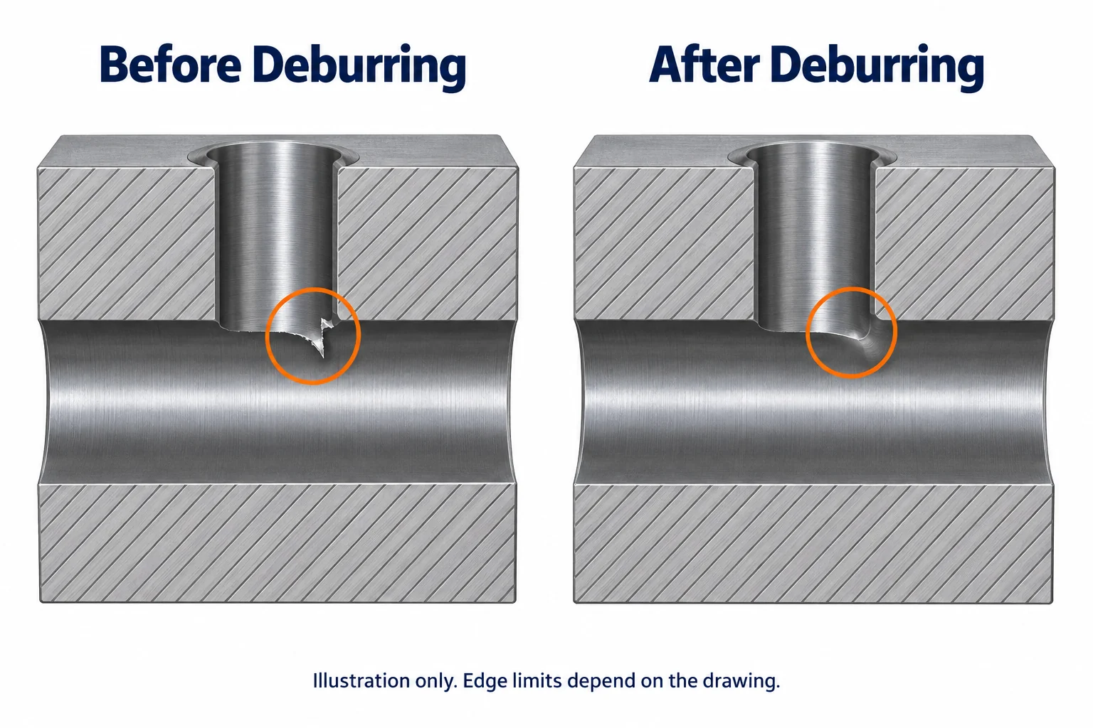
“Deburr all edges” communicates intent but may leave acceptance uncertain. Describe whether loose material, attached projections, or sharp remnants are unacceptable. Specify allowable edge break or radius where geometry affects function.
Avoid inventing a universal maximum burr height or radius. Suitable limits depend on the part, fluid circuit, mating components, and inspection capability. Excessive blending can also damage a metering edge or reduce a sealing land.
Separate burr removal from cleanliness. Removing an attached lip can create particles that still require extraction and cleaning. A smooth-looking edge does not prove the passage is clean.
Compare Cross Hole Deburring Methods
Choose the process using access, matériel, burr condition, allowable surface changes, and production quantity together.
| Method To Evaluate | Useful Starting Point | Limitation To Review |
|---|---|---|
| Dedicated mechanical tool | Repeatable accessible junctions | Tool geometry must fit the actual intersection |
| Flexible abrasive honing | Accessible bores needing edge blending | Bore finish, dimensional change, and cleaning need control |
| Thermal energy deburring | Complex internal passages with suitable burrs | Compatibilité des matériaux, residue removal, et qualification |
| Electrochemical deburring | Selected conductive-part edges | Electrode access, electrolyte handling, and dimensional control |
| Manual internal deburring | Accessible features and development work | Operator access, cohérence, and verification time |
Dedicated Mechanical Deburring
Mechanical tools remove burrs through controlled cutting contact. Suitability depends on bore ratio, offset, angle, and tool access.
HEULE’s cross-bore tooling information describes different solutions for particular intersection geometries. Treat those application envelopes as tool-selection inputs rather than promises for every cross hole.
Ask whether the tool can reach the full circumference of your junction. Review blade clearance, éloignement des puces, usure des outils, and nearby finished surfaces.
Flexible Abrasive Honing
Flexible honing can deburr cross-drilled intersections while changing the bore’s surface condition. Tool choice and operating conditions require validation on your material and geometry.
Brush Research’s cross-hole guidance describes this application and emphasizes appropriate lubrication. Do not assume a finishing tool will correct bore form or remove every heavy burr.
Check the bore after processing. Specify any restrictions on roughness, edge blending, abrasive residue, and dimensional change. Agree cleaning before final inspection or assembly.
Thermal And Electrochemical Processes
Specialized processes may reach features that are difficult to access with a cutting tool. They still require application-specific approval.
Extrude Hone’s manifold application guidance describes thermal deburring for internal passages. Evaluate material response, burr size, subsequent cleaning, and protected features before choosing it.
Electrochemical deburring uses localized electrochemical material removal on conductive parts. Ask the process provider to review electrode positioning, unintended removal, état de surface, and residue control.
Neither process should be assumed available for your order without explicit supplier confirmation. Include subcontractor responsibilities and validation costs in the quotation.
Plan Deburring Within The Manufacturing Sequence
Your process sequence should prevent later operations from recreating burrs or trapping contamination inside the finished part.
Start with the drilling sequence and tool condition. Reducing burr formation can simplify removal, but it does not eliminate the need for verification.
Agree whether deburring occurs before or after heat treatment, precision finishing, et revêtement. Consider material hardness, stabilité dimensionnelle, accéder, and any surfaces the process may affect.
Par exemple, finish machining after deburring may create another burr at the same junction. Installing plugs before cleaning may restrict access. The approved route should identify these dependencies.
Use this sequence as a planning framework:
- Machine the passages using the agreed route.
- Remove burrs using a validated method.
- Complete later operations that affect the junction.
- Clean accessible internal passages through defined access points.
- Inspect the final edge, alésage, and cleanliness requirements.
- Protect the accepted component during storage and shipment.
Adjust the sequence to your actual design. Validate the final delivered condition rather than only an intermediate operation.
Verify Internal Edges And Cleanliness Separately
Edge inspection, contrôle dimensionnel, and cleanliness testing answer different questions about a cross-drilled component.
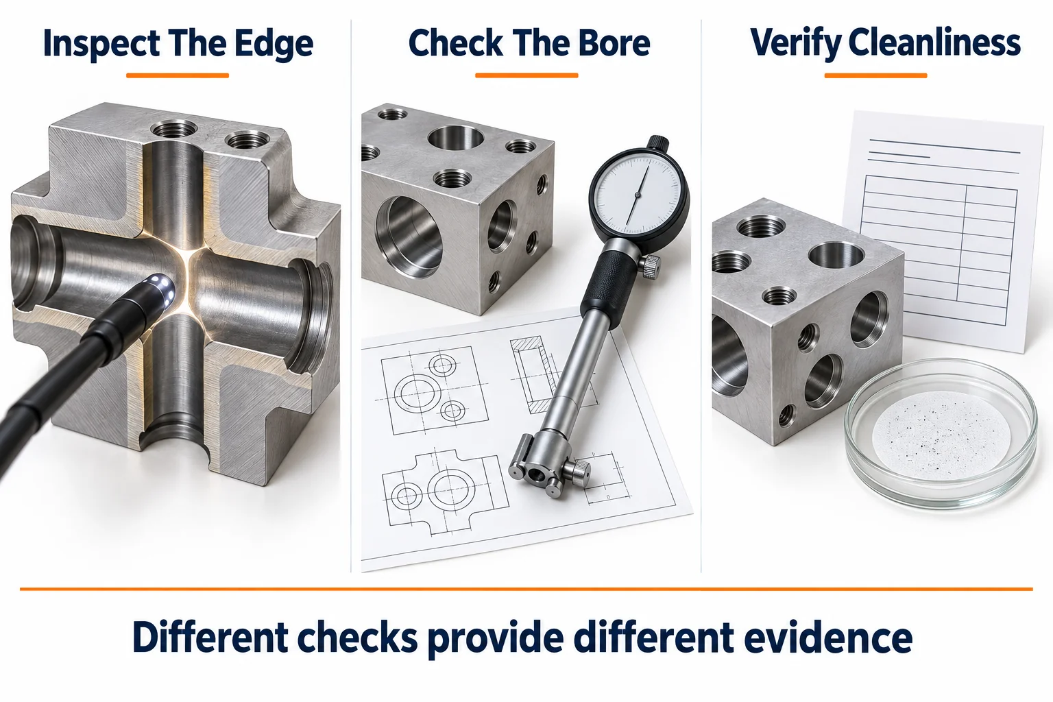
| Evidence | What It Helps Establish | What It Does Not Establish Alone |
|---|---|---|
| Borescope images | Visible condition at accessible junctions | Complete coverage behind blind spots |
| Development sectioning | Detailed edge condition on the sectioned sample | Every future production part’s condition |
| Bore measurements | Size and specified geometric features | Absence of internal loose particles |
| Agreed cleanliness test | Contamination under the specified extraction and analysis method | Edge geometry or burr attachment strength |
| Tests fonctionnels | Performance under the defined test conditions | Every possible latent defect |
For visual acceptance, define lighting, viewing direction, magnification where relevant, and reference images. Require enough views to cover the identified junction. Keep sample identity connected to the record.
For cleanliness, define the extraction method and acceptance criteria before quoting. State particle-size, quantité, mass, or other measures only when required by your application. A generic “clean” statement cannot substitute for an agreed test.
If inspection cannot reliably reach a feature, resolve that limitation before production approval. You may need representative sectioning, a different inspection method, or a design change.
Understand What Drives Cross Hole Deburring Cost
Cost follows feature accessibility, process development, production handling, nettoyage, and the evidence needed for release.
More junctions can increase cycle time and inspection coverage. Hard-to-reach features may need custom tooling or outside processing. Tight bore requirements can add measurements before and after deburring.
Compare quotations using the same scope. Include tool development, sample approval, nettoyage, rapports d'inspection, and batch traceability. A quote for external hand deburring is not equivalent to validated internal-edge control.
For changing designs or small releases, review development costs separately from repeat-part pricing. For stable production, discuss tool life assumptions and how wear will be monitored.
Questions fréquemment posées
Your acceptance requirements should distinguish the burr, the finished edge, the bore, and remaining contamination.
Is An Entrance Chamfer Enough For A Cross Hole
Généralement, an entrance chamfer addresses the accessible opening. It does not establish the condition where two internal bores intersect. Identify that junction separately.
Can Compressed Air Remove Internal Burrs
Compressed air may move some loose chips. It does not reliably remove attached metal or prove cleanliness. Choose removal and cleaning methods around the actual defect and passage geometry.
Can You Require No Burrs Without Specifying A Radius
You can define unacceptable projections without prescribing one radius everywhere. Still agree how the supplier will inspect that requirement. Add edge-removal limits where function depends on them.
Does Flexible Honing Replace Precision Bore Machining
Non. Treat it as a finishing or deburring operation within its validated application. Verify the specified bore geometry and finish separately.
Should Every Part Be Inspected Internally
Inspection coverage depends on failure risk, process capability, and your agreed quality plan. Discuss inaccessible areas and detection limits explicitly. Do not assume sample approval proves every later component.
Request A Cross Drilled CNC Part Review From TOPS
You can ask TOPS to review cross-drilled features as part of a custom CNC machining quotation.
Notre Services d'usinage CNC cover custom milled and turned components. Confirm the internal deburring method, inspection access, and any outside processing for your drawing.
Send the model, sectioned drawing, matériel, quantité, and identified bore intersections. Include edge limits, final bore tolerances, finition, cleanliness requirements, and required inspection records.
Request A CNC Part Review so the machining, débarquant, nettoyage, and verification scope can be discussed together.

