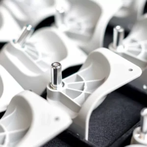
Les fils moulés sont des caractéristiques fondamentales dans d'innombrables produits, des biens de consommation et instruments de précision aux boîtiers industriels robustes. Bien que hautement souhaitable pour créer des, connexions reproductibles, l'intégration de fils directement dans un moule d'injection plastique présente des défis uniques. Des fils moulés réussis nécessitent un examen attentif des propriétés du matériau, forces mécaniques, et outillage complexe, s'écartant souvent considérablement des pratiques standard de moulage par injection.
L’objectif de ce guide est de fournir une analyse approfondie des, mécanique, et les exigences en matière d'outillage nécessaires pour intégrer avec succès des filetages moulés dans vos pièces en plastique.
Forces clés pertinentes pour la conception des filetages
Lors de la conception d'un filetage, deux forces mécaniques opposées doivent être maximisées ou minimisées pour garantir l'intégrité fonctionnelle et éviter les défaillances pendant l'utilisation.
UN. Force de traction (Résistance axiale)
Définition: La force linéaire requise pour séparer la fixation (vis) de la pièce moulée sans se retourner il. Celui-ci mesure la résistance du filetage au dénudage sous charge axiale directe..
Objectif de conception: La force d'extraction doit être le plus haut possible. Les parois filetées en plastique doivent être suffisamment solides pour résister à la charge de traction maximale attendue sans se briser avant que la fixation ne soit dévissée.. Cette force est dictée par la géométrie du filetage, la zone de contact, et la résistance au cisaillement du matériau.
B. Force de sortie du couple (Résistance rotationnelle)
Définition: Le couple de rotation requis pour retirer une vis une fois qu'elle a été complètement serrée ou « en place ».
Objectif de conception: Cette force devrait être le plus bas possible pour permettre facilement, montage et démontage reproductibles. Cependant, il doit être suffisamment haut pour maintenir la charge de serrage et empêcher le desserrage vibratoire. En pratique, la force de sortie de couple doit être facilement surmontée par des outils manuels mais suffisante pour résister aux contraintes opérationnelles. Le concepteur recherche un équilibre où une précharge optimale est obtenue (maximiser l'extraction) avec un minimum d'effort de retrait (minimiser la perte de couple).
Types de filetage pour moulage par injection et exigences en matière d'outillage
Types de filetage pour moulage par injection
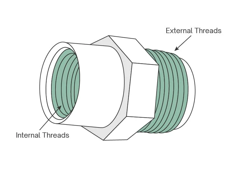
Le choix entre les filetages externe et interne détermine fondamentalement la complexité et le coût du moule en raison du défi que représente le démoulage des contre-dépouilles..
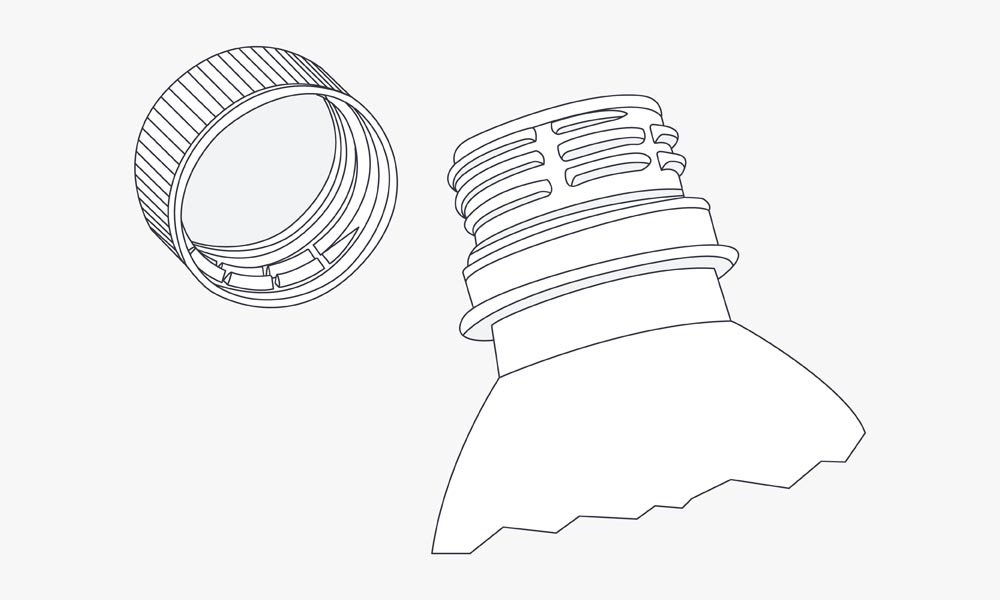
UN. Fils externes (Méthode la plus simple)
Difficulté de conception: Relativement facile. Les fils externes (comme sur un bouchon de bouteille) se former autour de la circonférence de la pièce.
Méthode: La forme du filetage est créée directement par la géométrie du moule : la vallée du filetage est formée par le cavité mur, et le sommet du fil est formé par le cœur mur. Aucun mouvement n'est strictement nécessaire pour démouler les fils eux-mêmes.
Inconvénient: Lignes de séparation: Parce que le filetage traverse la ligne de joint du moule, un visible et tactile ligne de séparation s'étendra le long de l'axe du fil. Même si les mouleurs expérimentés peuvent réduire le flash, la ligne reste une caractéristique permanente, affectant potentiellement l'étanchéité ou l'engagement précis.
B. Filetages internes (Méthode de contre-dépouille complexe)
Difficulté de conception: Beaucoup plus difficile. Les filetages internes représentent une contre-dépouille qui verrouille la pièce sur la broche centrale, nécessitant des mécanismes de démoulage spécialisés.
Méthode automatique principale: Déroulage du noyau / Dérouleur:
Mécanisme: Un mécanisme supplémentaire motorisé ou actionné hydrauliquement est ajouté à la base du moule. Ce noyau de déroulement (ou mécanisme de dévissage) fait pivoter la broche centrale hors de la pièce finie avant l'éjection.
Avantage: Pas de lignes de séparation sur les fils, garantissant une qualité de fil parfaite à 360 degrés. Temps de cycle courts.
Inconvénient: Augmente considérablement le coût du moule, complexité, entretien, et temps d'installation.
Méthode manuelle secondaire: Chargement manuel:
Application: Idéal pour la production de très petits volumes ou pour les threads extrêmement volumineux où l'automatisation n'est pas pratique.
Processus: Une tige filetée dédiée est placée manuellement dans le moule avant chaque cycle. Après injection, la pièce finie est éjectée avec la broche centrale toujours à l'intérieur. Un opérateur utilise ensuite un outil portatif pour dévisser manuellement le noyau de la pièce..
Inconvénient: Nécessite plusieurs broches principales pour laisser le temps au noyau métallique de refroidir avant la réinsertion. Entraîne des temps de cycle très lents et des coûts de main d’œuvre élevés.
Méthodes de libération de filetage pour les pièces finies
Méthodes de libération de filetage pour les pièces finies
Choisir la bonne méthode de démoulage équilibre le coût de l'outillage, temps de cycle, et la complexité des threads.
UN. Forcer la libération (Décapage) – Rarement utilisé
Mécanisme: Le moule s'ouvre, et les broches d'éjection poussent la pièce hors de la broche filetée.. Les fils sont étiré et dépouillé sur la broche centrale.
Applicabilité: Uniquement viable pour les petits threads (par exemple., pas fin sur les capsules de bouteilles flexibles) avec des matériaux ayant des propriétés d'allongement élevées (comme le PE ou le PP).
Conditions préalables critiques de conception:
Le profil du filetage doit intégrer des angles de dépouille (cône) et généreux rayons (rondeur) à la racine et à la crête du fil.
L'épaisseur de la paroi doit être cohérent et relativement fin pour permettre au plastique de fléchir sans se fissurer lors du décapage.
B. Insertion manuelle (Extractible) – Parfois utilisé
Mécanisme: (Voir la section II.B., Méthode de chargement manuel) Repose sur le travail de l'opérateur pour retirer les broches centrales après le cycle.
Compromis: Faible coût d’outillage initial mais coût opérationnel le plus élevé (travail) et temps de cycle le plus long. Le coût de la main d’œuvre le rend inefficace pour tout sauf le prototypage ou les séries très limitées.
C. Déroulage entièrement automatique – Le plus courant
Mécanisme: (Voir la section II.B., Déroulage du noyau) Utilise un moteur dédié (servo hydraulique ou électrique) synchronisé avec la séquence d'ouverture de la machine pour faire tourner mécaniquement les noyaux filetés hors de la pièce.
Avantage: Fournit les temps de cycle les plus courts et le débit le plus élevé, nécessaire pour les pièces de consommation à grand volume.
Considérations: La complexité et la précision des composants mobiles (engrenages, supports, moteurs) augmenter considérablement l’investissement initial. L'entretien et la réparation des moules sont également spécialisés et plus coûteux.
Facteurs critiques de conception et meilleures pratiques
L'attention portée à la mécanique et à la géométrie des matériaux est essentielle pour la durabilité des filetages..
UN. Taille et pas du filetage
La règle du fil en plastique: Les matières plastiques ont une résistance au cisaillement nettement inférieure à celle des métaux.
Recommandation: Les filetages internes doivent être conservés au moins 0.3 pouces (environ. 7.6 mm) en diamètre. Le plus grand diamètre augmente la surface de contact pour les forces de cisaillement.
Sélection de l'emplacement: Utilisez le pas le plus grossier possible (moins de fils par pouce/mm). Un pas plus grossier signifie que la charge est répartie sur des, racines de fil plus fortes, réduisant la probabilité de décapage.
B. Contre-dépouilles
Les fils sont un contre-dépouille hélicoïdale, verrouillage de la pièce au moule.
Élimination via des actions secondaires: Pour les filetages externes ou latéraux qui ne peuvent pas être démoulés par rotation, les concepteurs peuvent utiliser actions secondaires activées par la came ou des diapositives. Ceux-ci rétractent une partie du moule perpendiculairement à la direction d'ouverture pour dégager la contre-dépouille..
Compromis: Bien que efficace, les actions latérales augmentent considérablement le coût et la complexité de l'outillage initial et introduisent des lignes de joint supplémentaires là où l'action latérale rencontre le corps principal du moule..
C. Sélection des matériaux
Flexibilité matérielle, dureté, et la résistance chimique sont primordiales.
Matériaux préférés pour les filetages internes (Durabilité):
abdos (Acrylonitrile Butadiène Styrène): Bon équilibre entre rigidité et résistance aux chocs.
POM (Polyoxyméthylène, ou Delrin): Excellente force, rigidité, et faible friction (idéal pour les montages/démontages répétés).
Nylon (Polyamide): Haute ténacité et résistance à l'usure, ce qui le rend excellent pour les filetages porteurs.
Fils externes: Le choix du matériau est moins critique car la cavité du moule environnante offre un support uniforme.
D. Meilleures pratiques générales de moulage
Le succès des filetages dépend du respect des principes fondamentaux du moulage par injection:
Angles de projet: Indispensable sur tous les murs pour le démoulage; souvent incorporé dans la géométrie du filetage elle-même pour les méthodes de libération de force.
Épaisseur de paroi constante: Critique pour garantir un refroidissement uniforme, minimiser la déformation, et éviter les concentrations de contraintes autour de la fonction du filetage.
Conception du rayon: Utilisez toujours un rayon aux coins (racine et crête du fil) au lieu de coins pointus, car les coins pointus sont très sujets à l'apparition de fissures et à la rupture sous contrainte dans le plastique.
Alternatives rentables aux fils moulés
Lorsque les fils moulés s'avèrent trop coûteux ou complexes, considérez ces alternatives robustes:
Usinage de filetages dans une opération secondaire: La pièce est moulée sans le filetage, et une machine dédiée (comme un routeur ou un tour CNC) coupe le fil une fois la pièce refroidie. Cela ajoute une étape de traitement mais simplifie le moule.
Vis autotaraudeuses: L'utilisation de vis métalliques conçues pour couper ou former leur propre filetage lorsqu'elles sont enfoncées dans un espace sous-dimensionné., trou moulé non fileté. C'est bon marché et efficace mais ne convient pas aux démontages répétés.
Insert fileté surmoulé (Thermofixé ou ultrasonique): Inserts métalliques préfabriqués (noix) sont placés dans le moule, ou sont installés après moulage par soudage thermique ou par ultrasons. Cela fournit la résistance d'un fil métallique à l'intérieur du composant en plastique, offrant une excellente résistance à l’arrachement et une excellente durabilité pour un assemblage fréquent.
Conclusion
Les filetages moulés sont une caractéristique de grande valeur, mais leur intégration nécessite une compréhension nuancée du comportement plastique sous contrainte et de la dynamique opérationnelle d'outillages complexes.. En optimisant soigneusement la géométrie du filetage, sélectionner des matériaux appropriés comme l'ABS ou le POM, et choisir le bon mécanisme de libération (souvent une automatisation complète pour les volumes élevés), les concepteurs peuvent surmonter les défis inhérents. En cas de doute, consulter un mouleur par injection plastique hautement expérimenté est l'étape nécessaire pour équilibrer l'intégrité du filetage, temps de cycle, et un outillage rentable. Contactez-nous pour plus d'informations.
![]()