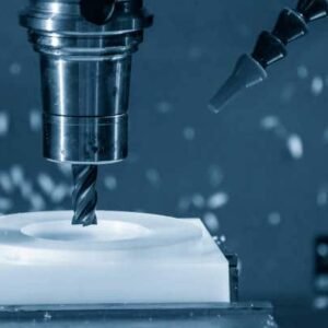
Les dessins techniques sont un élément essentiel du processus de fabrication. Si vous produisez Pièces usinées CNC, composants en tôle, produits moulés par injection, ou pièces moulées sous pression — un dessin technique bien préparé garantit que votre conception peut être fabriquée avec précision.
Dans ce guide, nous couvrirons tout ce que les ingénieurs doivent savoir sur la préparation de dessins techniques professionnels pour la fabrication, y compris les normes de dessin, éléments clés, Conseils sur les logiciels de CAO, et exigences de dessin spécifiques pour différents processus de fabrication.
Pourquoi les dessins techniques sont-ils si importants dans la fabrication?
Considérez un dessin technique comme un manuel d'instructions détaillé pour fabriquer votre produit.. Il indique à l'usine:
À quoi ressemble la pièce sous tous les angles
La taille exacte de chaque fonctionnalité
Quels matériaux utiliser
Dans quelle mesure la surface doit être lisse ou rugueuse
Dans quelle mesure certaines pièces doivent-elles être serrées ou lâches pour s'emboîter
Sans ces détails, l'usine doit deviner – et deviner peut conduire à des erreurs, retards, ou frais supplémentaires.
Les dessins techniques aident à éviter des erreurs coûteuses
La fabrication est une question de précision. Même une petite erreur de taille ou de forme peut causer de gros problèmes, en particulier pour les pièces utilisées dans les machines., voitures, ou électronique. Les dessins techniques garantissent que tout le monde, de l'ingénieur à l'opérateur de la machine, est sur la même longueur d'onde..
Les dessins techniques sont un langage universel
Une autre raison pour laquelle les dessins sont importants est qu'ils utilisent des symboles et des règles standard que les employés des usines du monde entier comprennent.. Si vos pièces sont fabriquées en Chine, Allemagne, ou aux USA, un dessin technique approprié permet d'éviter les problèmes de communication.
Les dessins techniques aident à contrôler la qualité
Enfin, les dessins techniques définissent les normes de qualité de votre produit. Ils indiquent exactement au fabricant ce que vous attendez et vous donnent un élément de vérification lorsque les pièces finies arrivent..
En bref, si vous voulez que votre produit soit réalisé correctement du premier coup – dans les délais et dans les limites du budget – ne sautez jamais le dessin technique!
Normes internationales pour les dessins techniques
Les normes de dessin technique sont comme les « règles du jeu ». Ils s'assurent que peu importe où vos pièces sont fabriquées - en Chine, Europe, ou l'Amérique - tout le monde comprend les mêmes symboles, mesures, et lignes directrices.
Sans ces normes, chaque entreprise peut dessiner les choses différemment, conduisant à la confusion, erreurs, ou des retards de production.
Les deux normes les plus courantes à connaître
Il existe deux systèmes principaux utilisés dans le monde pour les dessins techniques:
Normes ISO (Organisation internationale pour la normalisation)
Utilisé principalement en Europe, Asie, et bien d'autres parties du monde.
Se concentre sur les unités métriques (millimètres, centimètres).
Comprend des directives pour les types de lignes, symboles, dimensionnement, tolérances, et plus.
Normes communes:
OIN 2768 (Tolérances générales)
OIN 1302 (Texture de surface)
Normes ASME (Société américaine des ingénieurs mécaniques)
Utilisé principalement aux États-Unis.
Se concentre sur les unités impériales (pouces) mais prend également en charge la métrique.
Norme bien connue: ASME Y14.5 — c'est le guide incontournable pour le dimensionnement et le tolérancement géométriques (DG&T), ce qui aide à contrôler la forme, taille, et position des caractéristiques sur une pièce.
Pourquoi les normes sont-elles si importantes?
Imaginez envoyer votre dessin dans une usine à l’étranger – si vous n’utilisez pas de format standard, les ingénieurs pourraient ne pas comprendre vos symboles ou instructions. Cela peut conduire à:
Mauvaises tailles de pièces
Mauvaises finitions de surface
Emplacements incorrects des trous
Échec des contrôles de qualité
Mais lorsque vous suivez les normes ISO ou ASME, tout le monde parle le même « langage technique du dessin ». Cela rend le processus de fabrication plus rapide, Plus facile, et plus précis.
Conseil pour les ingénieurs et les concepteurs
Vérifiez toujours quelle norme préfère votre fabricant avant d'envoyer vos dessins. Par exemple:
| Région | Norme commune utilisée |
| Europe/Asie | Norme ISO |
| États-Unis/Canada | Norme ASME |
Suivre les bonnes normes démontre du professionnalisme et permet d'économiser du temps et de l'argent pour vous et votre usine..
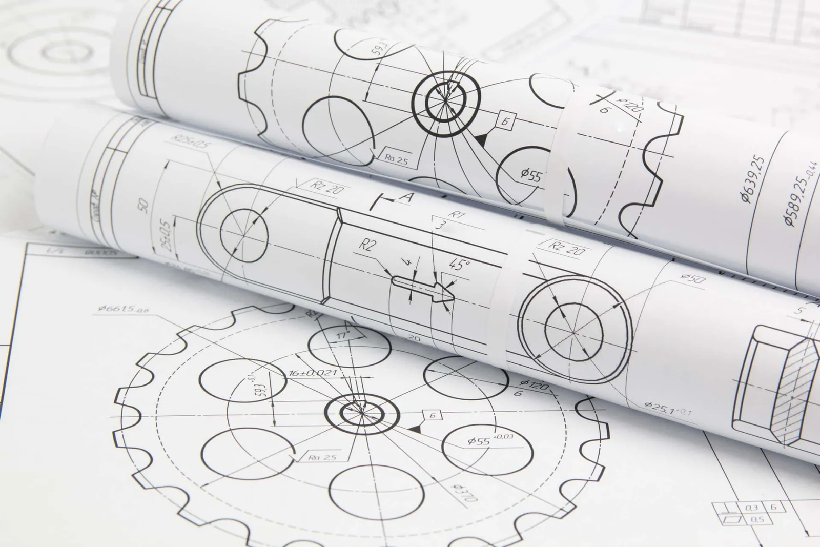
Éléments clés d'un dessin technique
Un dessin technique est plus qu'un simple croquis : c'est comme un manuel d'instructions détaillé pour fabriquer une pièce.. Chaque ligne, note, et le symbole a un but. Si quelque chose manque ou n'est pas clair, cela pourrait entraîner des erreurs ou des retards de production.
Décomposons les parties les plus importantes que tout bon dessin technique devrait avoir.
Bloc de titre
Cela se trouve généralement dans le coin inférieur droit du dessin.. Il fournit des informations de base comme:
Nom de la pièce
Numéro de pièce
Matériel
Échelle (quelle est la taille du dessin par rapport à la pièce réelle)
Date du dessin
Nom du concepteur ou de l’ingénieur
Historique des révisions (indique si le dessin a été mis à jour)
Considérez le cartouche comme la carte d'identité du dessin : il aide les gens à savoir ce qu'ils regardent..
Vues de la pièce (2D ou 3D)
La plupart des dessins montrent différentes vues d'une pièce pour donner une image complète. Les points de vue courants incluent:
Vue de face
Vue de dessus
Vue latérale
Vue en coupe (montre une coupe intérieure)
Vue isométrique ou 3D (facultatif mais utile)
Plusieurs vues aident l'usine à comprendre la forme, taille, et les détails de votre pièce sous tous les angles.
Dimensions
C'est l'une des parties les plus importantes de tout dessin technique. Les dimensions indiquent à l'usine exactement quelle doit être la taille de tout.
Les dimensions typiques incluent:
Longueur, largeur, hauteur
Taille et emplacement du trou
Épaisseur des murs
Rayon ou diamètre des courbes
Utilisez toujours des dimensions claires et précises. Si une usine doit deviner, c’est une mauvaise nouvelle.
Tolérances
Les tolérances indiquent au fabricant la variation autorisée dans la taille de votre pièce..
Par exemple:
Une taille de trou de 10 mm ± 0,1 mm signifie que le trou peut être compris entre 9,9 mm et 10,1 mm tout en restant OK..
Les tolérances sont importantes car aucun processus de fabrication n'est parfait : les pièces présentent toujours de petites variations. Mais plus la tolérance est stricte, plus le coût est élevé.
Symboles de finition de surface
Ces symboles montrent à quel point une surface doit être lisse ou rugueuse..
Par exemple:
Une pièce qui nécessite un polissage ou un usinage aura un symbole d'état de surface avec une valeur de rugosité spécifique (comme Ra 3,2 μm).
Sans ces symboles, l'usine ne saura pas si une surface doit être rugueuse, lisse, ou brillant.
Notes et instructions spéciales
Parfois, vous devrez ajouter des notes supplémentaires pour les éléments qui ne rentrent pas dans les autres catégories. Cela pourrait inclure:
Exigences matérielles
Instructions de traitement thermique
Revêtement de surface (comme l'anodisation ou la peinture)
Instructions de montage
Exigences en matière d'inspection de qualité
Un bon dessin doit répondre à chaque question avant qu’elle ne soit posée.
Aucune devinette. Aucune hypothèse. Aucune erreur.
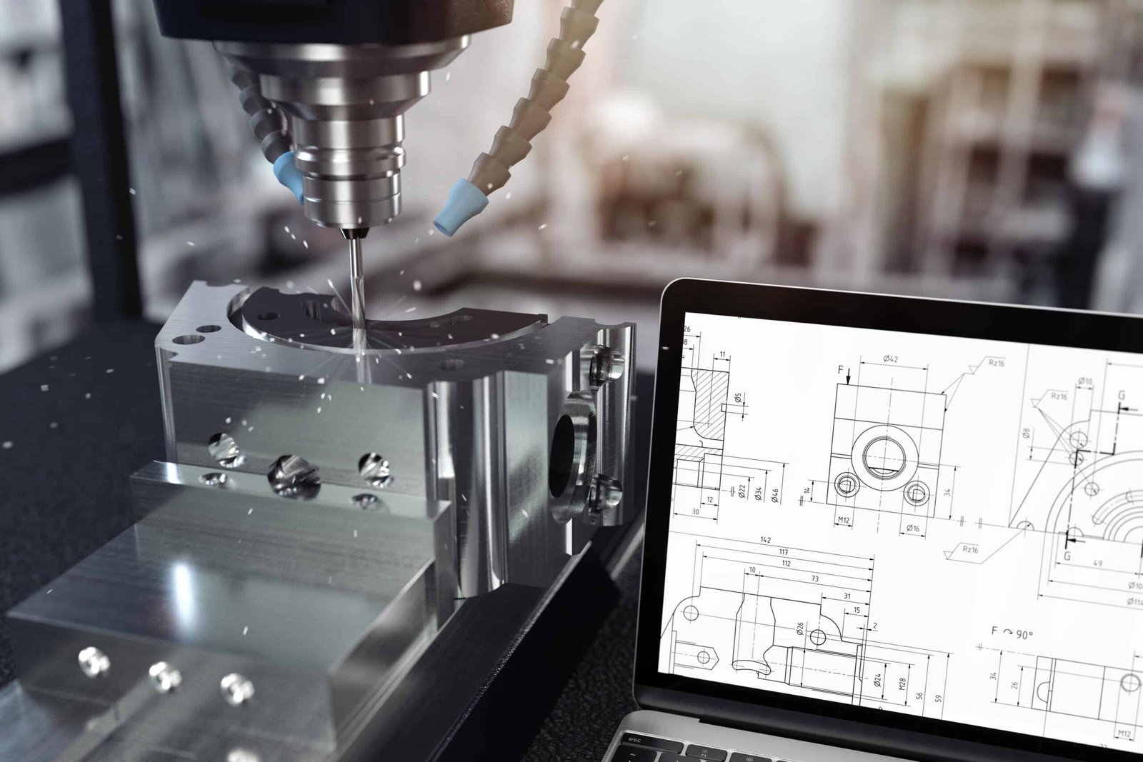
Préparer un dessin technique avec un logiciel de CAO
Si vous débutez en CAO, vous vous demandez peut-être : comment puis-je réellement faire un bon dessin technique?
Voici un guide simple étape par étape pour vous aider à démarrer.
Étape 1: Commencez avec un modèle 3D
Avant même de commencer votre dessin 2D, la plupart des ingénieurs créent un modèle 3D de la pièce dans leur logiciel de CAO (comme SolidWorks, Autocad, ou Fusion 360).
Ce modèle 3D vous donne:
La forme correcte de la pièce
Dimensions exactes
Une idée claire de son apparence et de son ajustement
Une fois que le modèle 3D semble bon, vous pouvez générer vos dessins techniques 2D directement à partir de celui-ci. Cela permet de gagner beaucoup de temps par rapport au dessin à partir de zéro..
Étape 2: Ajouter différentes vues
Après avoir créé votre modèle 3D, l'étape suivante consiste à insérer des vues 2D dans votre feuille de dessin.
Les points de vue courants incluent:
Vue de face
Vue de dessus
Vue latérale
Vue en coupe (si nécessaire pour montrer les détails intérieurs)
3D ou vue isométrique (facultatif, mais utile)
Choisissez les vues qui montrent le mieux les caractéristiques importantes de votre pièce.
Étape 3: Ajouter des dimensions
Une fois vos opinions en place, il est temps d'ajouter des dimensions. Soyez aussi clair et détaillé que possible.
N'oubliez pas d'inclure:
Taille globale (longueur, largeur, hauteur)
Positions et tailles des trous
Épaisseur de paroi
Rayons et angles
Mesures critiques qui affectent la fonction
Conseil de pro: N'ajoutez pas trop de dimensions inutiles : uniquement ce qui est nécessaire à la production..
Étape 4: Définir les tolérances
Après avoir ajouté des dimensions, vous devez définir des tolérances, en particulier pour les fonctionnalités importantes ou de haute précision.
Il existe deux manières de définir les tolérances:
Ajouter des tolérances spécifiques à côté d'une dimension
Ou, définir les tolérances générales dans le cartouche (Par exemple: ±0,1 mm sauf indication contraire)
Soyez intelligent ici : des tolérances serrées signifient des coûts plus élevés!
Étape 5: Ajouter des exigences en matière de matériaux et de surfaces
Suivant, indiquer à l'usine de quel matériau la pièce doit être faite, et à quoi devrait ressembler la surface.
Exemples:
Matériel: Aluminium 6061, Acier inoxydable 304, Plastique ABS
Finition de surface: Surface usinée Ra 3,2 μm
Revêtement: Anodisé, Peint, Brillant, etc..
Ces informations peuvent être placées dans le cartouche ou sous forme de note distincte..
Étape 6: Ajouter des notes et des instructions spéciales
Parfois, il y a des détails qui ne rentrent pas dans le dessin principal, comme:
Traitement thermique
Instructions de montage
Détails du traitement de surface
Normes d'inspection de la qualité
Exigences d'emballage
Ajoutez-les sous forme de notes claires sur le dessin.
Étape 7: Vérifiez tout soigneusement
Avant d'envoyer votre dessin à l'usine, revérifie tout:
Toutes les vues importantes sont-elles incluses?
Les dimensions sont-elles correctes?
Les tolérances sont-elles raisonnables?
Le matériau est-il spécifié?
Toutes les instructions spéciales sont-elles claires?
Erreurs dans le dessin = Retards, Coût plus élevé, ou de mauvaises pièces.
Les meilleurs dessins techniques sont faciles à comprendre, même pour les personnes qui ne parlent pas bien votre langue..
Évitez les détails inutiles. Utiliser des symboles standards. Et pensez toujours du point de vue de l’usine.
Un dessin clair fait gagner du temps, argent, et du stress pour tout le monde.
Exigences spécifiques pour différents processus de fabrication
Différentes méthodes de fabrication nécessitent différents types d'informations sur votre dessin technique.
Décomposons-le de manière simple.
Dessins d'usinage CNC - Ce qu'il faut inclure
L'usinage CNC utilise des outils de coupe pour enlever de la matière d'un bloc de métal ou de plastique..
Quelles usines veulent voir dans votre dessin:
Dimensions exactes de chaque élément
Tolérances pour les trous, machines à sous, platitude, etc..
Finition de surface (Par exemple, Ra 3,2 μm)
Filetages et trous taraudés (avec légendes standards)
Type de matériau
Toute exigence d'usinage particulière (comme des arêtes vives, chanfreins, ou ébavurage)
Conseil de pro: N'ajoutez des tolérances strictes que là où cela compte vraiment. Cela peut vite devenir cher!
Dessins de tôlerie – Ce qu'il faut inclure
Les pièces en tôle sont réalisées par pliage, Coupe, et poinçonnage de tôles plates.
Que montrer sur votre dessin:
Vue à plat (avant de plier)
Courber les lignes et les directions
Rayon et angles de courbure
Tailles et positions des trous
Épaisseur du matériau
Traitement de surface (comme le revêtement en poudre ou l'anodisation)
Conseil de pro: N'oubliez pas que plier le métal étire ou comprime légèrement le matériau. Ajoutez donc une note sur les tolérances de pliage si nécessaire..
Dessins de moulage par injection – Ce qu'il faut inclure
Le moulage par injection concerne les pièces en plastique fabriquées en injectant du plastique fondu dans un moule..
Choses importantes à montrer:
Angles de projet (généralement 1°–3°) pour aider à démouler la pièce
Épaisseur de paroi (une épaisseur uniforme est préférable)
Nervures et structures de support pour plus de solidité
Emplacements des portes et des broches d'éjection (si nécessaire)
Type de matériau (abdos, PC, Nylon, etc.)
Finition de surface (brillant, mat, texturé)
Conseil de pro: Si vous n'êtes pas sûr des angles de dépouille ou de la conception du moule, demandez conseil à l'usine - ils le font tous les jours.
Dessins de moulage sous pression – Ce qu'il faut inclure
Le moulage sous pression est utilisé pour fabriquer des pièces métalliques (comme l'aluminium ou le zinc) aux formes complexes.
Détails clés à ajouter:
Angles de projet (similaire au moulage par injection)
Épaisseur de paroi (éviter trop épais ou trop fin)
Congés ou rayons pour éviter les angles vifs
Type de matériau (Aluminium ADC12, alliage de zinc, etc.)
Finition de surface (tel que moulé, grenaillé, peint)
Toutes zones d'usinage après coulée
Conseil de pro: Les pièces moulées sous pression nécessitent souvent un usinage supplémentaire pour des surfaces de précision ; montrez-le clairement dans votre dessin..
Chaque processus de fabrication a ses propres règles.
Avant d'envoyer votre dessin, demandez-vous:
"Si je faisais cette pièce avec ce processus, qu'est-ce que j'aurais besoin de savoir?"
Clair, des dessins simples aident l'usine à fabriquer vos pièces plus rapidement, moins cher, Et avec moins d'erreurs.
Derniers conseils pour les ingénieurs
Les dessins techniques sont la base d’une fabrication réussie. Un dessin bien préparé garantit que vos pièces sont produites correctement, rapidement, et dans le budget.
En suivant les normes internationales, en utilisant des techniques de CAO appropriées, et personnalisation des dessins pour des processus de fabrication spécifiques, les ingénieurs peuvent éviter des erreurs coûteuses et fournir des produits de haute qualité.
Liens internes:
Explication des bases du dessin technique
Moulage par injection vs usinage CNC: Quelle est la différence?
Comprendre la finition de surface dans la fabrication
![]()