

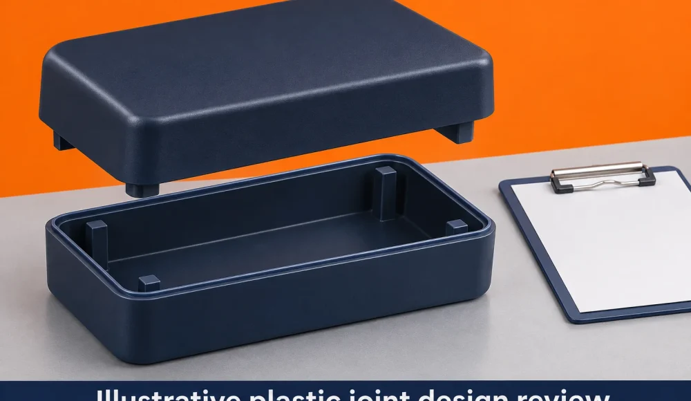
Ultrasonic welding joint design should be reviewed before you release injection mold tooling. Choose the joint around your resin, enclosure geometry, tooling access, et conditions d'acceptation. A welded appearance alone cannot establish strength or leak performance. Agree the assembly trial and inspection plan before production.
Define The Weld Requirement Before The Joint
Your joint must satisfy a defined assembly requirement, y compris la force, scellage, apparence, and final dimensions.
Start with the loads and environments your assembly will encounter. Identify whether the enclosure needs permanent closure, fluid containment, or only retention.
Specify permitted flash, visible marks, alignement, and the assembled height. Identify sensitive internal components that could be affected during welding.
A strong joint and a leak-tight joint require different evidence. A pull test cannot automatically establish the permitted leakage rate.
For broader process selection, voir notre plastic joining overview. This guide focuses on molded joint design after ultrasonic welding becomes a candidate.
Compare Energy Director And Shear Joint Concepts
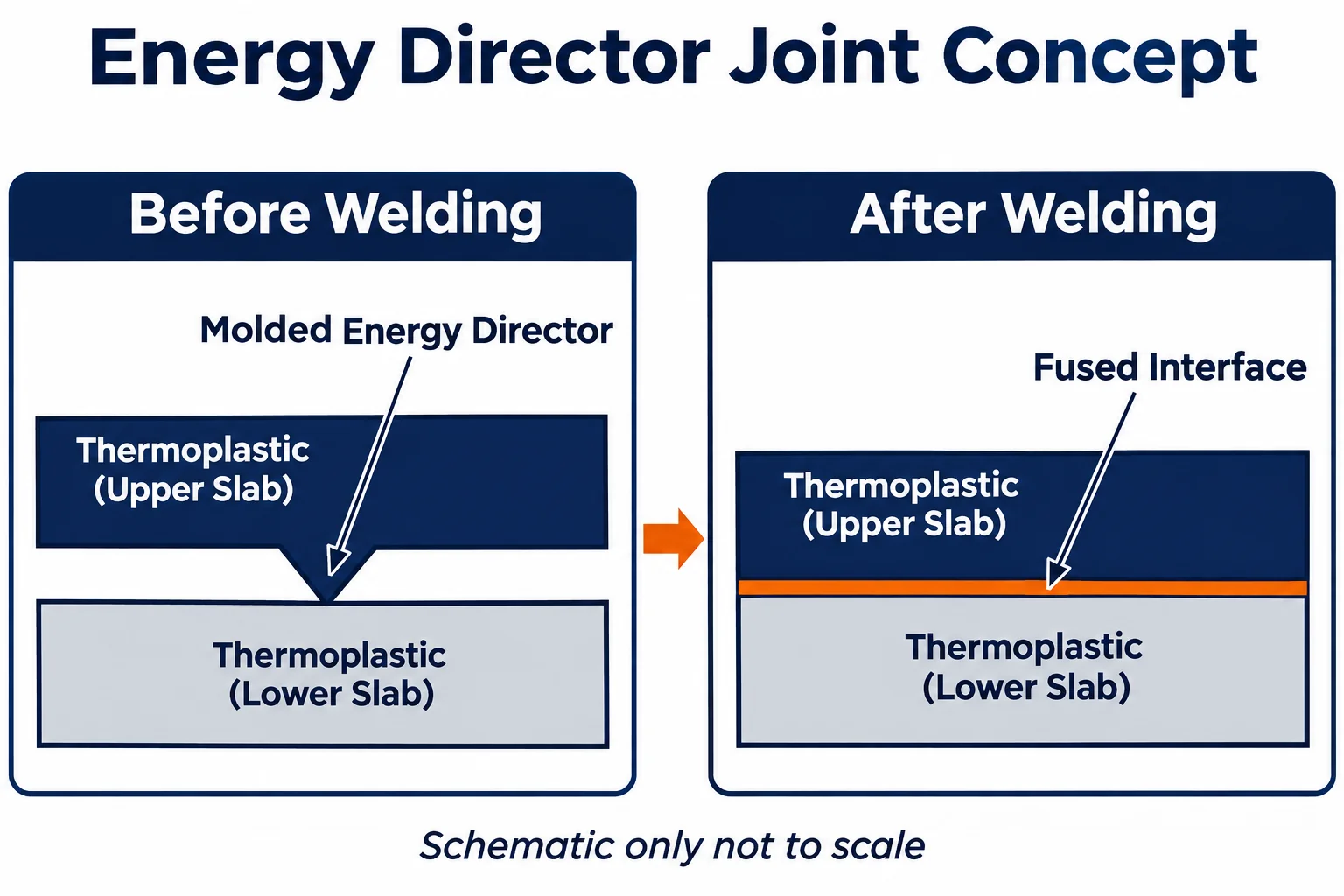
An energy director localizes initial contact, while a shear joint uses controlled interference as the components telescope together.
A conventional energy director is a small molded ridge. Its initial contact concentrates heating, allowing material to melt across the interface.
Dukane’s ultrasonic assembly guide explains energy directors, joint variations, and part support. Use its recommendations as design inputs requiring application review.
| Joint Concept | Design Purpose | Review Before Approval |
|---|---|---|
| Butt joint with energy director | Localize heating at a small initial contact | Alignement, melt flow, exposed flash, and required strength |
| Step or tongue and groove | Add location and space to manage the joint interface | Moldability, remaining wall thickness, and available weld area |
| Shear joint | Melt an interference interface during controlled insertion | Interference, wall support, collapse, and resin suitability |
No joint name guarantees a sealed assembly. Select the concept with your resin supplier and welding equipment specialist.
Use Resin Specific Guidance Instead Of Generic Dimensions
You should qualify the actual resin grades and joint geometry together rather than copying a universal ridge size.
The polymer family is only the starting point. Record the grade, fournisseur, charges, color package, and any permitted material changes.
Eastman’s processing and mold design guidelines favor shear joints for the polymers covered. Their advice illustrates why a generic energy director is not suitable for every resin.
Confirm whether your proposed material combination can form the required bond. Similar appearance or similar melting behavior does not establish compatibility.
Do not assume a successful trial transfers unchanged to another grade. Include the material identity in the approved assembly specification.
Provide Horn Access And Fixture Support
Your molded parts need accessible horn contact and stable fixture support so welding motion reaches the intended interface.
Reserve a suitable contact surface before adding cosmetic texture or obstructing features. Review the horn approach with the complete assembly model.
Support the lower component near the joint. A flexible wall can move instead of maintaining the intended interface contact.
TWI’s component design guidance connects joint selection with geometry, résine, horn distance, and fixture support. Review these factors together.
Show any electronics, membranes, loose inserts, or delicate features in the assembly model. Ask the specialist to assess their exposure during trials.
Control The Molded Features That Set The Weld
You should identify the molded dimensions that govern fit, contact, alignement, and final collapse.
Specify the energy director or interference geometry on the controlled drawing. Define its relationship to locating features and inspection datums.
Check mating part flatness and fit before using welding adjustments to compensate. Warpage or inconsistent contact can create uneven assembly behavior.
Account for movement during welding in the assembled dimension stack. Keep the pre-weld condition separate from the final acceptance dimensions.
Define where displaced material may go. Include any flash trap, internal clearance, and surfaces that must remain clear.
Qualify The Assembly With Production Representative Parts
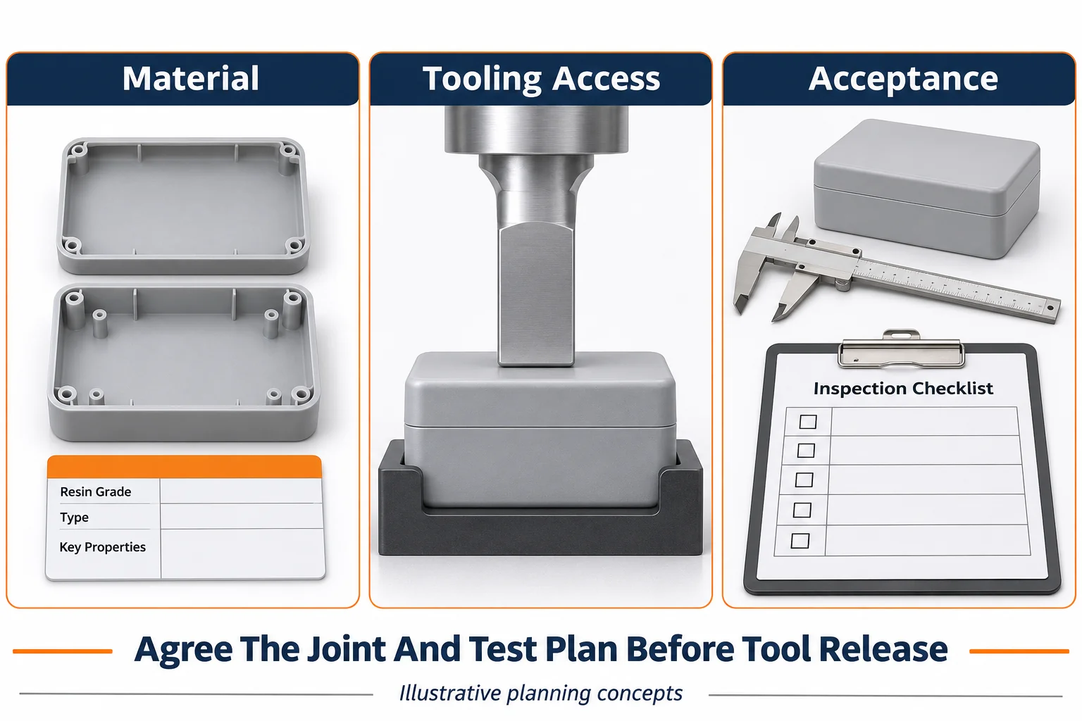
Your approval trial should use representative molded parts, final tooling contact, and the agreed acceptance tests.
Prototype geometry can reveal access problems. It cannot establish production weldability when its material or manufacturing route differs.
Record the molded part revision, resin identity, cavité, fixation, horn, and proposed machine settings. Retain the trial conditions with the results.
Evaluate more than a single favorable sample. Agree which material and dimensional variation the qualification must represent.
| Acceptance Question | Preuve d'accord |
|---|---|
| Does the assembly carry its required load | Defined load direction, test method, et limite d'acceptation |
| Does it meet the sealing requirement | Test medium, pression, durée, and permitted leakage |
| Does it fit the next assembly | Final dimensions, la date, et état d'inspection |
| Is its appearance acceptable | Reference sample, permitted marks, and flash locations |
| Can the approved process be repeated | Controlled recipe, monitoring limits, and response to deviations |
Process readings support control; they do not replace product acceptance. Define what a rejected cycle means for the affected assembly.
Request Comparable Molding And Assembly Quotes
Your quotation should separate molded part supply, welding development, outillage, qualification, and ongoing inspection.
TOPS fournit services de moulage par injection de plastique. Send the mating parts together so molding decisions can account for the proposed assembly.
Ask which party owns the joint design, horn, fixation, and approval trials. Confirm the proposed assembly route and responsibility before ordering.
Costs depend on geometry, résine, nombre de cavités, tooling access, portée de l'essai, and test requirements. Avoid comparing a parts-only quote with qualified assembly supply.
If your product needs repeated opening, reconsider a permanent welded closure. Resolve serviceability before committing the mold design.
Questions fréquemment posées
You should resolve joint geometry and acceptance questions before tooling release.
Does Every Ultrasonic Weld Need A Triangular Energy Director
Non. Shear joints and other designs use different interfaces. The joint must suit the resin, géométrie, and assembly requirements.
Does A Tongue And Groove Guarantee A Seal
Non. It can help location and flash management, but sealing still requires suitable design, traitement, et vérification.
Can I Add The Joint After The Mold Is Built
Parfois, but changes can affect wall thickness, ajuster, outillage, et l'apparence. Review assembly requirements before mold manufacture.
Can A Printed Prototype Prove Weld Strength
Not for a different production material or process. Use production representative molded parts for the agreed qualification.
Can The Same Settings Be Used After A Resin Change
Do not assume so. Review material changes against the approved qualification and repeat trials when the change requires them.
What Should I Send For An Assembly Review
Send both component models, dessins, resin grades, dimensions finales, charges, sealing needs, exigences cosmétiques, and internal component details.
Request A Molded Joint Design Review
Contactez-nous with your mating part files, exigences en matière de résine, quantité, volume annuel, et la vie du programme. Include the proposed welding route and acceptance tests. Agree the molded joint and assembly responsibilities before tooling approval.