



CNC flatness inspection should verify the specified surface under agreed support, moderazione, copertura, and evaluation conditions. A single indicator reading or roughness value cannot establish surface flatness. Define the inspection plan before ordering, especially for thin plates, sealing faces, and mounting surfaces.
Define The Surface Flatness Requirement
Your drawing should identify the controlled surface, tolleranza, and governing drawing standard.
Surface flatness controls how a surface fits between two parallel planes. It does not require a datum reference. Parallelism adds an orientation relationship to a datum, so the two requirements answer different questions.
KEYENCE explains flatness measurement, including contact measurement and the importance of coverage.
A smooth surface can still bow across its length. Allo stesso modo, a flat surface can retain machining texture. Specify surface texture separately when function requires it. Do not substitute an Ra value for a flatness requirement.
Avoid choosing a universal tolerance from another component. Your design authority should establish the requirement from the joint, foca, mounting arrangement, and operating conditions.
Distinguish Flatness From Orientation And Thickness
Your acceptance plan should separate surface form, orientamento, and the distance between opposing surfaces.
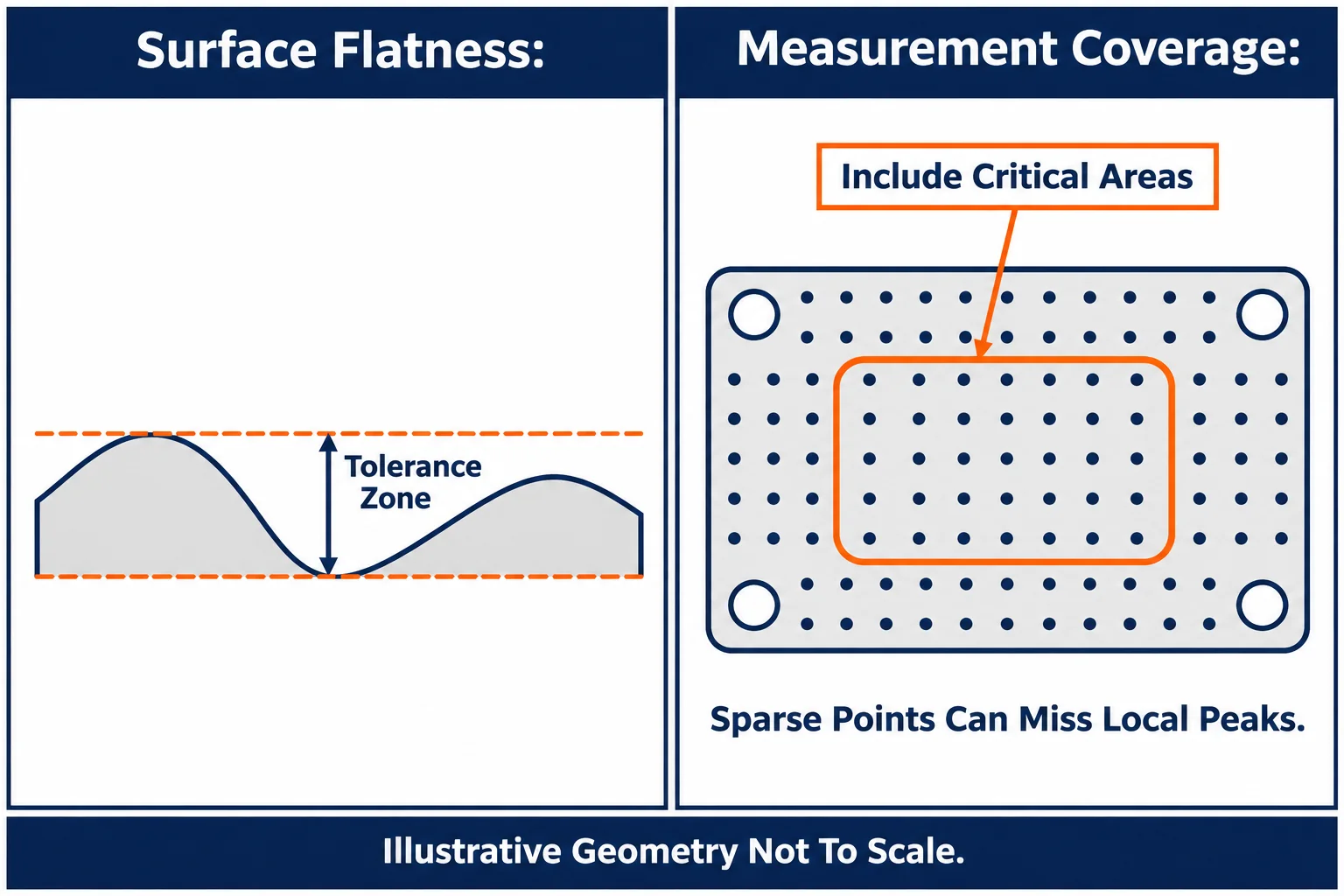
For surface flatness, the tolerance zone can orient around the evaluated surface without referencing another feature. A raw height range in an arbitrary machine alignment may include surface tilt.
Ask how the inspection software evaluates the measured surface. Record the evaluation method and any filtering or excluded data. Do not assume different reports use equivalent settings merely because both display “flatness.”
Thickness measurements between two faces answer another question. Several consistent thickness readings do not establish that either face is flat. If assembly needs opposing faces parallel, review that requirement explicitly.
A contact indicator setup also needs a suitable alignment procedure. The goal is to evaluate surface form rather than unintentionally measure orientation to the supporting table.
Agree The Support And Restraint Conditions
Your inspection setup should preserve the condition required by the drawing.
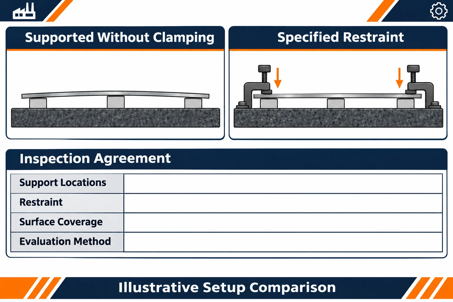
A thin part can change shape when supported, clamped, or pressed against a fixture. A result obtained under restraint may differ from a result without clamping. Neither condition should be selected simply because it produces a preferred reading.
Define the part orientation, support positions, and permitted restraint. If your drawing requires inspection in a specified restrained condition, document the fixture and loading procedure. If no restraint is permitted, avoid forcing the face against a reference surface.
Renishaw's fixturing guide discusses supporting and clamping workpieces. Use a documented setup that prevents movement without introducing unintended deformation.
A repeatable fixture does not automatically represent the required acceptance condition. Review the setup with the design and quality teams before accepting production reports.
Plan Coverage Across The Functional Surface
Your measurement strategy should cover the controlled area and credible local deviations.
Sparse points can miss a local peak, pocket edge, or bowed region between them. Choose point locations or scan paths according to the surface geometry and manufacturing risks. A universal point count cannot establish adequate coverage for every part.
Include relevant regions around holes, sezioni sottili, and interrupted surfaces. Define how boundaries, Champhers, and deliberately recessed areas are treated. Do not quietly exclude difficult regions after seeing the results.
Compare contact probing, scanning, and suitable optical measurement against your actual surface. Consider access, material response, measurement capability, and data processing. More collected points do not remove systematic setup errors.
Keep the coverage plan with the inspection program. If buyer and supplier results differ, compare the sampled areas before deciding the component changed shape.
Check The Reference Equipment And Part Condition
Your inspection process should account for the reference equipment, pulizia, and thermal condition.
A granite plate is a measurement reference with its own calibration requirements. Mitutoyo's surface plate bulletin distinguishes overall flatness from local variation. Confirm that the reference equipment supports the required measurement.
Remove loose contamination from support and contact locations using an appropriate procedure. A chip beneath a support can change the setup. Do not remove a genuine part defect merely to improve the reading.
Define the relevant thermal condition and allow the part to stabilize as required by the procedure. The related Guida alla temperatura di ispezione CNC discusses temperature agreement for dimensional inspection.
Record the delivery stage being evaluated. Inspection before stress-relieving operations, finitura, or coating may not represent the final delivered condition.
Require A Flatness Report You Can Compare
Your report should identify the surface, impostare, copertura, evaluation, and result.
| Inspection Detail | Agree Before Production | Retain In The Report |
|---|---|---|
| Controlled Area | Drawing revision and surface extent | Feature identification |
| Part Condition | Final operation and restraint state | Actual condition inspected |
| Supporto | Orientation and support locations | Setup reference or photograph |
| Copertura | Points or scan paths and exclusions | Program revision and coverage |
| Valutazione | Method and approved data processing | Settings and measured result |
| Accettazione | Tolerance and decision procedure | Disposition and deviations |
Ask for the measured value and units, rather than only a pass statement. Where useful, request a surface map with its scale and orientation. Treat a colored map as supporting information, not a substitute for the result and procedure.
For a disagreement, compare fixtures, temperatura, copertura, and evaluation settings before changing the manufacturing process. Preserve the original evidence and obtain authorized disposition for disputed parts.
Confronta preventivi con lo stesso ambito di ispezione
Your quotation comparison should include the required final condition and inspection effort.
TOPS Precision fornisce Servizi di lavorazione CNC. Submit the flatness requirement with your complete drawing. Confirm the proposed process, dispositivo, inspection method, and reporting scope for the actual component.
A thin mounting plate may need different handling from a rigid block. Tighter requirements can increase process planning and verification effort. Discuss material condition, geometria, sequenza di finitura, quantità, and acceptance evidence before comparing prices.
Do not assume every flatness target requires grinding. Ask the supplier to propose a process that can meet your drawing and verification requirements.
Domande frequenti
Your flatness decision depends on the controlled surface and agreed inspection conditions.
Does Surface Flatness Require A Datum
NO. Surface flatness is a form control without a datum reference. Parallelism controls orientation relative to a datum.
Can A Surface Roughness Result Prove Flatness
NO. Roughness and overall surface form describe different characteristics. Specify both when the application needs both.
Can Clamping Change A Flatness Result
SÌ, especially for flexible components. Inspect under the condition required by the drawing and agreed procedure.
Request A Flatness Inspection Review
Contattaci con il tuo disegno, materiale, spessore, quantità, final finish, and flatness requirement. Identify sealing or mounting areas and required restraint conditions. Agree the inspection scope before releasing your CNC order.