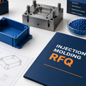



Wire thread inserts for CNC parts require a matched insert, prepared holding thread, installation procedure, and acceptance plan. Specify the complete system before machining. The finished screw size alone does not define the parent hole, insert length, locking behavior, or inspection requirements.
Specify The Insert System On Your Drawing
Your drawing should identify the approved wire insert and the finished thread it must provide.
A wire insert is a formed coil installed into a prepared holding thread. The mating screw engages the insert inside the parent component. This differs from a solid threaded bushing or a heat-set insert for plastic.
Identify the thread designation, insert product or approved equivalent, installed length, materiale, and required locking type. State whether the insert is a planned production feature or an authorized repair. A repair substitution should not silently change an approved design.
Record the governing specifications and drawing revision. If equivalents are permitted, define the characteristics that must remain equivalent. A matching nominal screw size alone is insufficient.
Choose Free Running Or Screw Locking Deliberately
Your insert selection should distinguish an ordinary running thread from a specified locking function.
Bollhoff's wire insert guide describes free-running and screw-locking designs. Screw-locking versions introduce a locking region that affects the mating screw’s running resistance.
If locking behavior matters, agree the applicable torque requirements and test procedure for the selected system. Include the mating screw, lubrication condition, and reuse expectations where relevant.
Do not treat screw installation resistance as direct proof of joint preload or insert retention. These are different acceptance questions. Ask the design authority to define the evidence required for the actual joint.
Avoid substituting a locking insert simply because it fits the same nominal thread. Confirm compatibility with the intended fastener and tightening process before approving the change.
Prepare The Correct Holding Thread
Your machining plan should use the hole preparation specified for the selected insert system.
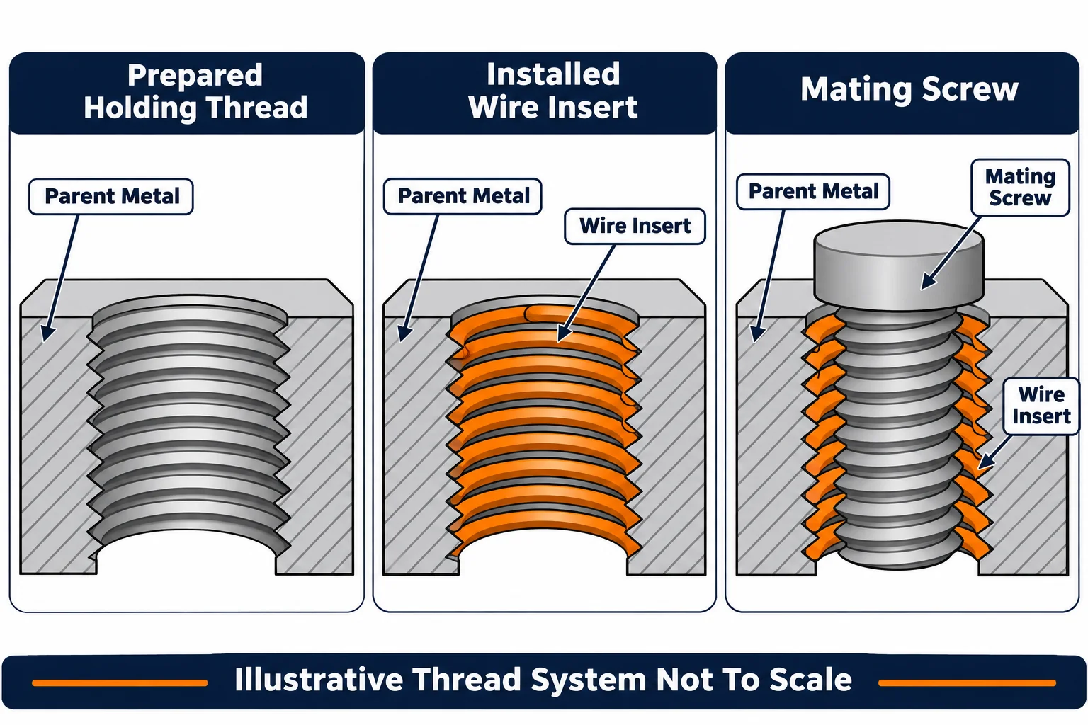
Common wire insert systems use a screw thread insert holding thread, often called an STI thread. That parent thread differs from the finished internal thread presented to the screw.
Bollhoff's installation guidance specifies system tools and gauges for checking the prepared holding thread. Do not substitute a standard finished-thread tap merely because the screw designation matches.
Agree drilling, entry preparation, usable threaded depth, and inspection before installation. For blind holes, distinguish the drill depth from usable holding thread and insert space. Include the clearance needed by the chosen tooling and final screw.
Use the insert manufacturer’s current data for the exact size and series. Avoid applying one generic drill diameter or installation depth to every wire insert.
Review The Parent Component And Processing Sequence
Your component design should accommodate the holding hole and the complete installed joint.
Review available wall thickness, geometria del capo, distanza dal bordo, hole position, and service loading with the design authority. A wire insert does not compensate for an unsuitable parent component.
Check whether coating, anodizzazione, or another finishing process affects the prepared thread or installed assembly. Agree which operations occur before installation and how protected features are handled.
Confirm the final screw engagement and blind-hole clearance. A screw that bottoms in the hole may feel tight without establishing the intended joint condition.
Keep material and finish changes under review. The insert, parent metal, fastener, and environment form one assembly. Do not assume a previous approval applies after changing one of those elements.
Define Installation Position And Tang Control
Your installation procedure should establish the approved insert position and any required tang disposition.
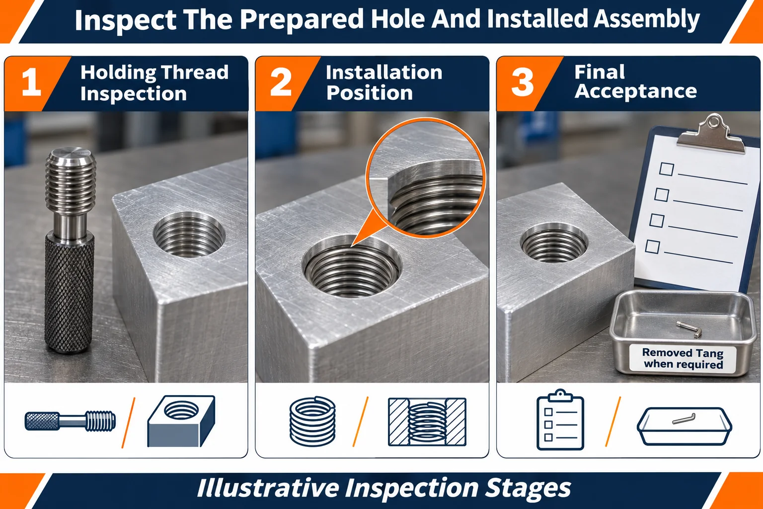
Specify the installed position relative to the component face using the chosen system’s instructions. Define how the operator detects incomplete insertion, protruding coils, cross-threading, or other installation defects.
Some wire inserts use an installation tang. Others use tangless designs with dedicated tooling. Bollhoff's tangfree guide describes a system that avoids the tang removal step.
When tang removal is required, define removal, recovery, and verification. This matters especially where loose material could enter an assembly or fluid passage. Breaking a tang does not establish that it has left the component.
A tangless design removes that particular tang concern, but still requires installation and cleanliness controls. Confirm the chosen product’s actual requirements rather than applying one procedure to every insert.
Inspect The Prepared Hole And Installed Assembly
Your acceptance plan should verify both the holding thread before installation and the finished assembly afterward.
A successful final screw trial does not explain whether the holding hole was correctly produced. Preserve the required pre-installation inspection evidence.
After installation, check insert identity, posizione, condizione, and tang status where applicable. Define final thread verification according to the product’s instructions. Locking and free-running designs may require different acceptance procedures.
Agree any functional, ritenzione, or torque testing separately. Specify test articles, limiti di accettazione, campionamento, and whether testing consumes or alters product. Do not invent a universal pullout load for every insert and parent material.
Record the part identifier, insert batch where required, procedure revision, inspection results, e deviazioni. Define the response to damaged inserts or holding threads before production starts.
Compare Quotes For The Complete Installed Feature
Your quotation comparison should include the insert, hole preparation, installazione, ispezione, and any authorized rework.
TOPS Precision fornisce Servizi di lavorazione CNC. Submit the insert specification with your drawing. Confirm the proposed tooling, installation arrangements, and reporting scope for your actual component.
| Requisito | Define Before Quoting | Evidence To Agree |
|---|---|---|
| Insert Identity | Product, materiale, lunghezza, locking type | Approved item and traceability |
| Holding Hole | Preparation and usable depth | System-specific inspection |
| Installazione | Position and tooling procedure | Installed condition check |
| Tang Control | Required disposition | Removal and recovery record |
| Final Thread | Verification method and condition | Inspection results |
| Test funzionali | Application-specific acceptance | Approved test report |
Repeated installation, additional testing, or difficult access can affect cost and delivery. Separate production inserts from repair allowances. Do not assume every rejected thread can receive another insert without engineering approval.
For protected surfaces and loose-item control during delivery, review the related parts packaging guide.
Domande frequenti
Your purchasing decision should cover the installed feature rather than only the insert’s nominal size.
Is The Holding Thread The Same As The Finished Screw Thread
NO. Common wire insert systems require a dedicated holding thread. Follow the selected manufacturer’s preparation and gauging instructions.
Does A Tangless Insert Eliminate Inspection
NO. It avoids the tang removal step, but installation position, condizione del filo, and cleanliness still require verification.
Can You Replace A Free Running Insert With A Locking Version
Only after approval for the actual joint. Locking behavior can affect the fastener and tightening procedure.
Request An Insert Installation Review
Contattaci con il tuo disegno, parent material, insert specification, quantità, mating fastener, e requisiti di ispezione. Identify blind holes, critical surfaces, and tang restrictions. Agree the complete installed feature before releasing your CNC order.