



The mechanical performance of a 3D printed component depends on the interaction between material properties, part geometry, wall thickness, infill, print orientation, layer adhesion, process parameters, and application loads. For FDM parts in particular, build orientation and interlayer bonding can have a significant effect on mechanical properties.
So, how do you make 3D printed parts stronger without unnecessarily increasing material consumption, weight, cost, and production time?
This guide explains the most important factors manufacturers and product engineers should consider when designing and producing stronger 3D printed parts.
What Determines the Strength of a 3D Printed Part?
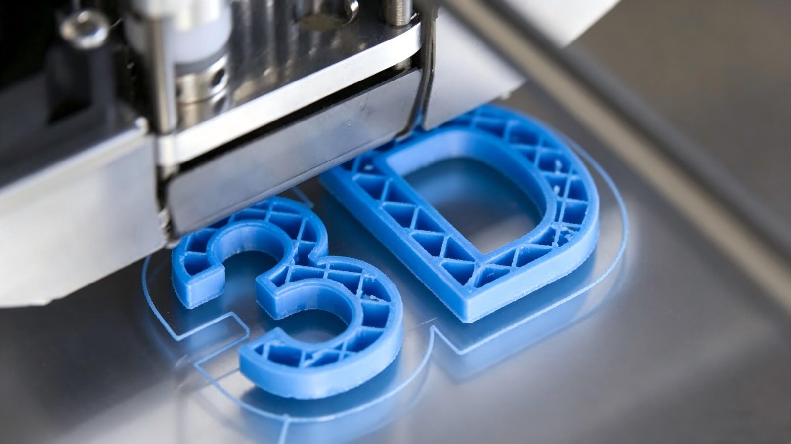
There is no single setting that determines whether a 3D printed component will be strong or weak.
A better way to think about part strength is:
Material + Geometry + Orientation + Walls + Infill + Process Parameters + Quality Control
Understanding how these factors interact is essential when producing functional parts rather than decorative models.
Material Selection: Start With the Right 3D Printing Material
Material selection should be one of the first decisions when designing a functional 3D printed component.
Different materials provide different combinations of:
Tensile strength
Stiffness
Impact resistance
Flexibility
Heat resistance
Chemical resistance
Wear resistance
Fatigue resistance
Dimensional stability
For example, nylon is commonly selected for components requiring toughness, wear resistance, and repeated mechanical loading, while carbon-fiber-reinforced polymers are often selected when high stiffness-to-weight performance is important.
PLA: Good for Prototypes and General-Purpose Parts
PLA is one of the easiest materials to print and is widely used for:
Concept models
Visual prototypes
Fixtures
Low-stress components
Demonstration parts
Its advantages include good stiffness, ease of printing, and relatively good dimensional stability.
However, PLA is not always the best choice for parts exposed to high temperatures, impact, or continuous mechanical loading.
PETG: Tough and Versatile
PETG provides a useful combination of:
Toughness
Moderate flexibility
Chemical resistance
Ease of printing
It can be suitable for functional prototypes, housings, brackets, protective covers, and many general industrial components.
ABS: Good for Heat and Impact Resistance
ABS is commonly used when a component needs better impact and temperature performance than PLA.
However, ABS is more sensitive to thermal contraction and warping, so printer enclosure and thermal management can become important.
Nylon: Toughness and Mechanical Durability
Nylon is particularly useful for parts that experience:
Repeated impact
Friction
Mechanical stress
Wear
Flexing
It is commonly considered for gears, hinges, brackets, moving components, and other functional parts.
One important consideration is moisture. Nylon is hygroscopic, so moisture control is essential for consistent printing quality and mechanical performance.
Carbon-Fiber-Reinforced Materials
Carbon-fiber-filled materials can significantly increase stiffness and reduce deformation.
The important point is that the strongest material is not necessarily the best material. The correct choice depends on the actual operating environment and mechanical requirements.
How to Increase 3D Printed Part Strength Through Design
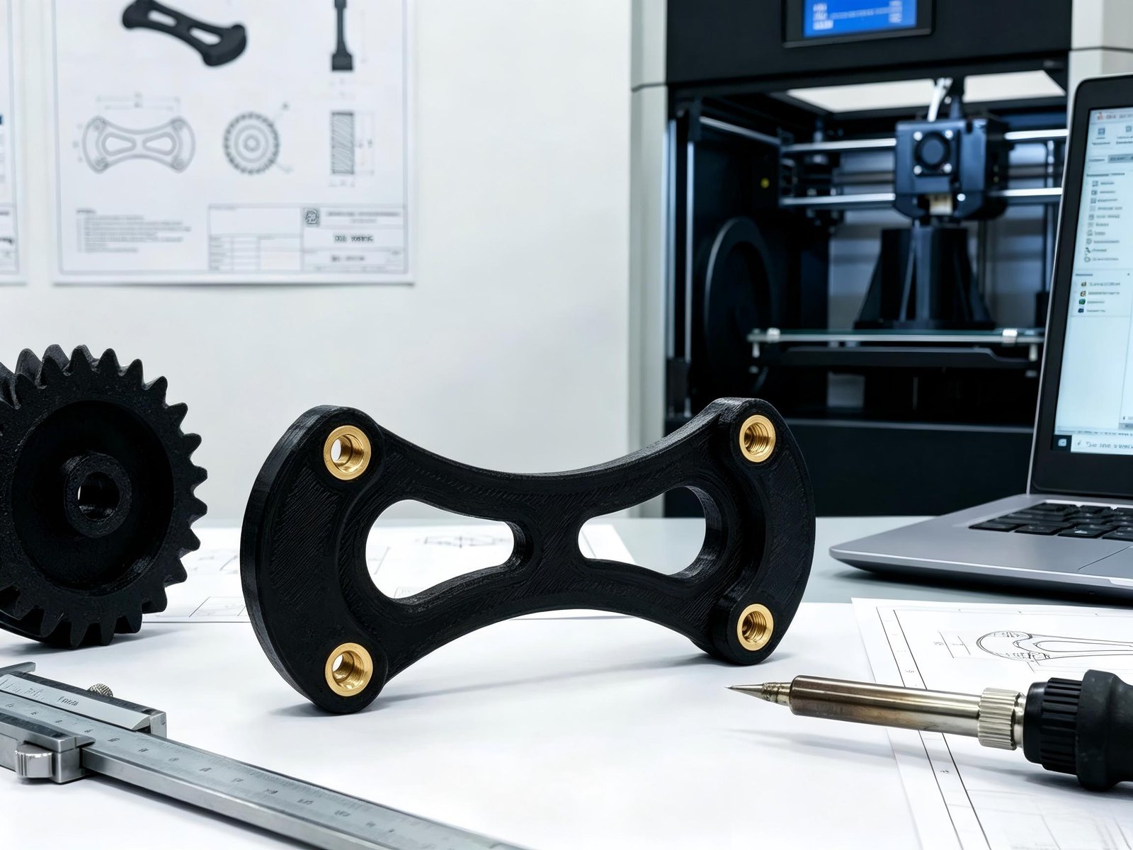
Material selection is only part of the solution.
A well-designed part can often achieve better performance without simply increasing the amount of material used.
Increase Wall Thickness
The external walls of an FDM component can have a major influence on its mechanical performance.
Increasing wall thickness can improve resistance to:
Bending
Cracking
Impact
Local deformation
Tensile loading
For many parts, increasing the number of perimeters can be more efficient than simply increasing infill.
This is why a strong 3D printed component should not be designed around infill percentage alone.
Increase the Number of Perimeters
Perimeters are the outer extrusion lines that form the shell of the component.
Increasing perimeter count can strengthen:
Brackets
Mounting points
Housings
Structural walls
Edges
Holes
The optimal number depends on geometry and loading, but the engineering principle is straightforward:
Use the shell strategically to carry external loads, rather than filling the entire internal volume unnecessarily.
This is also why 100% infill should not automatically be considered the strongest solution. In many FDM designs, outer walls have a major influence on bending, tensile, and torsional performance.
Add Fillets to Reduce Stress Concentration
Sharp internal corners can create stress concentrations.
When a component is subjected to bending or cyclic loading, these areas can become crack initiation points.
For mechanical components, this is often a more effective design improvement than simply increasing infill.
Reinforce High-Stress Areas
Not every region of a part needs the same amount of material.
More material where the load occurs + less material where it does not.
That principle is especially valuable when the objective is to reduce weight and manufacturing cost.
Does Higher Infill Make a 3D Printed Part Stronger?
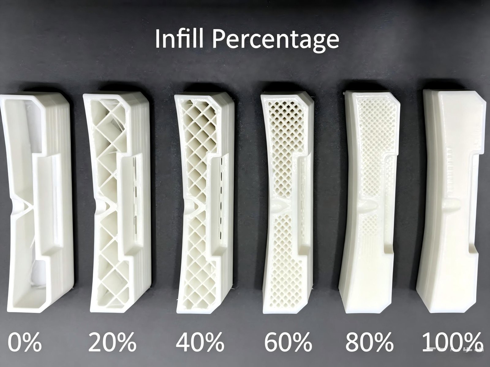
Generally, increasing infill can increase structural support and compression resistance, but higher infill does not automatically produce proportionally higher strength.
For example, increasing a component from 20% to 40% infill may produce a useful performance improvement, while increasing it from 70% to 90% may provide much less additional benefit relative to the additional material and print time.
Current practical guidance also emphasizes that more infill does not always mean a stronger part, particularly when wall thickness and load paths have not been optimized.
What Infill Density Should You Use for Strong 3D Printed Parts?
There is no universal infill percentage.
As a starting framework:
| Application | Starting Infill Range | Typical Priority |
| Decorative models | 0–15% | Speed and material savings |
| Visual prototypes | 10–20% | Appearance and speed |
| General prototypes | 15–30% | Balanced performance |
| Functional parts | 20–40% | Strength and efficiency |
| Heavy-duty components | 40–60%+ | Structural performance |
| Highly compressed components | 60–100% | Compression resistance |
These are starting points rather than guaranteed engineering specifications.
For a critical component, the correct density should be established through design analysis, prototype testing, or application-specific validation.
Choosing the Right Infill Pattern
Density is only one part of the equation.
The internal geometry can also influence how loads are distributed throughout the component.
Gyroid
Gyroid provides a continuous three-dimensional structure and is often considered for functional components requiring multi-directional support.
Cubic
Cubic creates a three-dimensional lattice and can be useful for mechanical components subjected to complex loads.
Grid
Grid is relatively simple and can provide an effective balance between strength and print efficiency.
Rectilinear
Rectilinear uses relatively simple linear paths and can be useful when printing speed and material efficiency are important.
Concentric
Concentric follows the shape of the external walls and can be useful for specific geometries and flexible applications.
The important principle is:
Do not select an infill pattern simply because it is marketed as “strong.” Select it according to the actual load case.
Research has also shown that both infill pattern and build orientation influence the mechanical properties of FDM parts, reinforcing the importance of evaluating the entire printing strategy rather than a single slicer parameter.
Wall Thickness vs. Infill: Which Should You Increase First?
This is one of the most common questions when trying to strengthen an FDM part.
In many cases, increasing wall thickness or perimeter count is a better first step than dramatically increasing infill.
Consider a bracket that fails because the external wall cracks around a mounting hole.
Increasing infill from 20% to 60% may add significant material inside the bracket without adequately addressing the crack location.
Print Orientation Has a Major Effect on Strength
FDM parts are inherently anisotropic because they are built layer by layer.
This means the mechanical behavior can differ depending on the direction of the applied load relative to the printed layers.
If the load is applied in a direction that tends to separate layers, the component can be significantly weaker than if the load is carried primarily within the deposited filament paths.
Therefore, print orientation should be considered during CAD design—not after the design is finished.
A practical design process is:
Expected load → Load direction → Part orientation → Layer direction → Structural geometry
For example, if a bracket is expected to experience bending, the orientation should be selected so that the critical load is carried as effectively as possible by the printed structure.
Build orientation is a recognized factor in FDM mechanical performance, alongside infill pattern and process parameters.
How Printing Temperature Affects Part Strength
Temperature directly affects material flow and interlayer bonding in thermoplastic printing.
If the nozzle temperature is too low:
Material may not flow properly
Layer bonding can be poor
Under-extrusion can occur
Voids may appear
If the temperature is too high:
Over-extrusion may occur
Geometry can become less accurate
Stringing may increase
Material degradation may become a concern
Therefore, the correct temperature should be established according to the specific material, printer, nozzle, and process conditions.
How Print Speed Affects Strength
High printing speed can improve productivity, but excessive speed can compromise deposition consistency and layer bonding.
For stronger parts, consider:
Reducing speed in critical areas
Maintaining adequate melt flow
Ensuring sufficient thermal bonding
Matching speed to nozzle diameter and material
A production process should balance:
Strength + Cycle Time + Dimensional Accuracy + Cost
The objective is not necessarily the slowest print.
It is the fastest process that consistently meets the required specifications.
Cooling and Layer Adhesion
Cooling has a particularly important role in thermoplastic printing.
Too much cooling can reduce interlayer bonding in some materials, while insufficient cooling can create:
Deformation
Poor bridging
Overheating
Dimensional problems
Material-specific cooling profiles are therefore important.
For example, materials such as ABS and nylon generally require different thermal management strategies from PLA.
Common Problems That Make 3D Printed Parts Weak
Warping
Warping occurs when thermal contraction causes portions of the part to lift or deform.
Possible solutions include:
Heated build plate
Enclosure
Better bed adhesion
Appropriate print orientation
Material-specific thermal control
Weak Bed Adhesion
If the first layer does not adhere properly, the entire part can be compromised.
Under-Extrusion
Under-extrusion means insufficient material is deposited.
The result can be:
Voids
Weak walls
Poor layer bonding
Incomplete infill
Poor Layer Bonding
If adjacent layers do not bond properly, the component may split along layer lines.
When the failure follows the layer interface, simply increasing infill may not solve the problem. The process itself needs to be corrected.
How to Make 3D Printed Parts Stronger Without Increasing Cost
A strong part does not necessarily need to contain more material.
Instead, optimize the material where it provides the greatest structural benefit.
1. Optimize Print Orientation
Changing orientation may improve strength without increasing material consumption.
2. Increase Perimeters
Adding one or two additional perimeters can sometimes provide more useful reinforcement than a large increase in infill.
3. Add Ribs and Fillets
Improve the load path through geometry rather than simply adding bulk.
4. Use Local Reinforcement
Concentrate material around mounting holes, corners, and load-bearing areas.
5. Select a More Suitable Material
A tougher or stiffer material may provide better performance than simply increasing the quantity of a weaker material.
6. Use Variable or Adaptive Infill
High-density infill can be concentrated in critical areas while less important areas remain lightweight.
This approach can reduce:
Material consumption
Weight
Printing time
Production cost
while maintaining the required performance.
Which 3D Printing Process Is Best for Strong Functional Parts?
FDM is not the only additive manufacturing technology available.
The best process depends on the required combination of:
Strength
Accuracy
Surface finish
Material
Production volume
Part size
Geometry
Cost
FDM 3D Printing
FDM is attractive because of its:
Broad thermoplastic material selection
Relatively low cost
Simple digital workflow
Suitability for prototypes and functional components
SLA / Resin 3D Printing
SLA can provide excellent:
Surface finish
Fine details
Dimensional resolution
However, resin mechanical properties vary significantly by formulation and application.
SLS
SLS is particularly useful for polymer functional parts with complex geometries.
Nylon-based SLS materials can provide strong, durable components without conventional support structures.
MJF
Multi Jet Fusion is another option for functional polymer parts. Current manufacturing guidance commonly positions nylon-based MJF as suitable for demanding functional applications where more uniform properties are desirable.
Therefore, if mechanical performance is critical, the question should not simply be:
“What infill should I use?”
It should be:
“Which material and additive manufacturing process are best suited to the required performance?”
3D Printed Parts for Prototyping vs. End-Use Applications
The optimization strategy changes according to the purpose of the part.
Rapid Prototypes
Main priorities:
Speed → Cost → Basic Functionality
Low-to-medium infill and fast printing parameters may be appropriate.
Functional Prototypes
Main priorities:
Mechanical Performance → Dimensional Accuracy → Cost → Speed
The material, orientation, walls, and infill need more careful optimization.
End-Use Parts
Main priorities:
Reliability → Mechanical Performance → Repeatability → Environmental Resistance
For these applications, engineering validation becomes much more important.
Examples of real-world functional 3D printed applications include automotive brackets, drone components, jigs, fixtures, electronic enclosures, hinges, and replacement machine components.
Frequently Asked Questions About Strong 3D Printed Parts
What is the strongest material for 3D printing?
There is no single strongest material for every application. Nylon and carbon-fiber-reinforced polymers are frequently considered for demanding functional components, while materials such as PETG and ABS can be better choices for specific combinations of toughness, temperature resistance, cost, and printability.
Does higher infill make a 3D print stronger?
Generally, higher infill can improve certain aspects of mechanical performance, but the relationship is not linear. Wall thickness, print orientation, material, and layer adhesion can be equally or more important depending on the load case.
What is the best infill density for strong 3D printed parts?
There is no universal value. A practical starting point for many functional parts is around 20–40%, but demanding components may require substantially more or may benefit more from additional perimeters and better geometry.
Is wall thickness more important than infill?
For many FDM components, increasing wall thickness or perimeter count can be a very effective way to improve strength, particularly for bending, tension, and loads concentrated near external surfaces.
What is the strongest 3D printing infill pattern?
There is no universal strongest pattern. Gyroid, cubic, grid, and other patterns have different structural characteristics. The correct choice depends on geometry, loading direction, material, and print orientation.
Does print orientation affect 3D printed part strength?
Yes. FDM parts are built layer by layer, so mechanical properties can vary with build orientation and layer direction.
How can I improve layer adhesion?
Start by checking nozzle temperature, extrusion, cooling, print speed, and material moisture. Moisture-sensitive materials such as nylon require particular attention to drying and storage.
Why are my 3D printed parts brittle?
Potential causes include:
Unsuitable material
Excessive cooling
Poor layer bonding
Under-extrusion
Incorrect temperature
Moisture
Poor print orientation
Stress concentrations in the CAD design
The correct solution depends on where and how the part is failing.
How can I make a 3D printed part stronger without making it heavier?
Focus on structural efficiency rather than simply adding material.
Possible approaches include:
Better print orientation
Additional perimeters
Fillets
Ribs
Local reinforcement
Stronger materials
Optimized infill
Variable-density structures
Can 3D printed parts be used as end-use components?
Yes. With appropriate material selection, manufacturing technology, design optimization, process control, and validation, 3D printed components can be used for functional and end-use applications. Current industrial applications include brackets, fixtures, housings, hinges, tooling, and replacement machine components.
Conclusion: Strong 3D Printed Parts Require More Than Higher Infill
Producing stronger 3D printed parts is not simply a matter of increasing infill to 50%, 80%, or 100%.
The best results come from optimizing the entire manufacturing system:
Material + CAD Design + Wall Thickness + Infill + Print Orientation + Temperature + Speed + Layer Adhesion + Quality Control
The most effective approach is therefore not:
“How much more material can I put into this part?”
It is:
“Where does this part need strength, what causes it to fail, and what is the most efficient way to reinforce it?”
For an engineering evaluation, provide your 2D drawing or 3D CAD file, material requirement, estimated quantity, critical tolerances, and application/load requirements. This allows Tops Precision to recommend the appropriate 3D printing process and optimize the design for strength, dimensional accuracy, cost, and production repeatability.


