


Mold repairs restore an approved tool condition. Mold modifications change that condition to meet a revised requirement. Before authorizing either, identify the cause, compare repair and replacement options, and define sample approval. This guide focuses on plastic injection molds and the decisions that affect production recovery.
Mold Repair Vs Mold Modification
Repair returns a tool toward its approved condition, while modification changes its intended geometry or operation.
The distinction controls your drawings, quotation, and acceptance requirements.
| Work Type | Typical Purpose | Approval Basis |
| Maintenance | Clean, lubricate, or service components before failure | Maintenance requirements and documented condition |
| Repair | Restore a damaged feature or replace a worn component | Existing approved tool and part requirements |
| Modification | Change a dimension, feature, gate, or operating arrangement | Approved engineering change and revised requirements |
| Replacement | Renew an insert, major assembly, or entire tool | New scope, compatibility checks, and qualification |
For example, replacing a broken core pin to its original specification is a repair. Changing its diameter is a modification.
One job can include both. Separate the scopes so you know which original requirements remain and which have changed.
Diagnose The Problem Before Cutting Steel
Confirm that the mold causes the defect before choosing a repair method.
A rejected molded part does not automatically prove tooling damage. Material preparation, processing conditions, handling, and measurement can also contribute.
Compare current production with the last approved run. Check whether the issue affects one cavity, several cavities, or every part.
| Symptom | Tooling Checks | Other Factors To Review |
| Flash | Shutoff damage, contamination, alignment, and wear | Packing conditions, clamping, and material behavior |
| Short shot | Gates, vents, obstructions, and hot-runner condition | Fill settings, resin condition, and machine performance |
| Drag marks | Surface damage, draft, and ejection alignment | Cooling, release conditions, and handling |
| Dimensional drift | Core wear, cavity damage, and component movement | Resin changes, process shifts, and measurement conditioning |
| Longer cooling or warpage | Cooling passages, leakage, and circuit condition | Water supply, cycle settings, and material variation |
Use the table to organize investigation, not to assign a cause from appearance alone.
Preserve defective samples, acceptable reference parts, process records, and cavity identification. These often reveal more than a photograph alone.
Ask the toolmaker to document findings before corrective machining. Otherwise, the original evidence may disappear during cleaning or rework.
Common Injection Mold Repair Methods
Select the method according to damage location, tool material, remaining geometry, and the required surface condition.
Replacing Worn Or Damaged Components
Core pins, ejector components, guide elements, seals, and suitable inserts may be replaced when their surrounding interfaces remain serviceable.
Check the mating features as well as the failed item. A new pin in a worn or misaligned guide may fail again.
Specify the component material, hardness where relevant, fit, and functional clearances. Confirm compatibility with the existing tool assembly.
Precision Machining And EDM
Machining or EDM can restore selected features or prepare a location for a replacement insert.
First confirm that removing material will preserve strength, cooling clearance, and the intended molded geometry.
The finishing plan matters. Do not assume an EDM-machined surface is ready for every cosmetic or functional application.
Ask which surfaces require subsequent finishing and dimensional verification. Include the inspection datums in the approved repair scope.
Repair Welding
Welding can add material where machining alone cannot restore the required shape. Suitability depends on the steel and repair conditions.
Uddeholm publishes different welding recommendations for different grades, material conditions, and welding methods. These include filler selection and thermal treatment. Uddeholm tool-steel welding guidance
Before approving welding, identify the steel grade and available heat-treatment history. Review prior welds, crack extent, and proximity to critical features.
Laser welding is not automatically suitable for every damaged mold. Ask how the proposed procedure manages cracking, distortion, and local property differences.
Polishing And Surface Restoration
Polishing may address suitable surface damage after the underlying condition is assessed. It also removes material, so geometry must remain controlled.
More polishing does not always improve a surface. Uddeholm identifies orange peel and pitting as possible overpolishing problems. Uddeholm polishing guidance
For textured or high-gloss parts, approve the finish on molded samples. A repaired tool surface can reproduce differently in plastic.
Filler compatibility also matters when welded surfaces require polishing or texturing. Uddeholm specifically highlights this relationship. Mold-steel selection and repair considerations
Cooling And Hot-Runner Repairs
Cooling work may involve cleaning passages, correcting leakage, or replacing serviceable circuit components after diagnosis.
Hot-runner faults require checks specific to the installed system. A temperature error can originate in sensing, wiring, heating, or control components.
EWIKON’s controller documentation distinguishes these fault categories. Use the applicable equipment manual rather than assuming the mold cavity needs repair. EWIKON controller troubleshooting
Agree on pressure, flow, electrical, or operating checks appropriate to the actual repair. Do not substitute a visual check for functional verification.
Which Mold Modifications Are Feasible?
A modification is feasible when the existing tool can support the revised geometry, functions, and validation requirements.
Start with an overlay of the old and new part models. Identify every changed surface and the corresponding tool feature.
Understand Steel Removal And Steel Addition
The direction of a part change determines whether tool material must be removed or added.
For a simple external dimension, enlarging the cavity may enlarge the molded feature. That generally involves removing tool material.
For a hole formed by a core pin, reducing pin diameter makes the molded hole smaller, subject to shrinkage.
Making that hole larger usually requires a larger core feature. Replacing a removable pin may be simpler than adding material.
These examples explain geometry, not a machining allowance. Final dimensions require a review of shrinkage, tolerances, and trial results.
“Steel-safe” planning leaves material available for an anticipated adjustment. It does not make every later design change easy.
Use Replaceable Inserts Where The Tool Supports Them
A revised insert may localize a change and preserve the main mold structure.
However, the pocket, support, retention, cooling, and shutoff interfaces still require review. New interfaces can create additional fitting requirements.
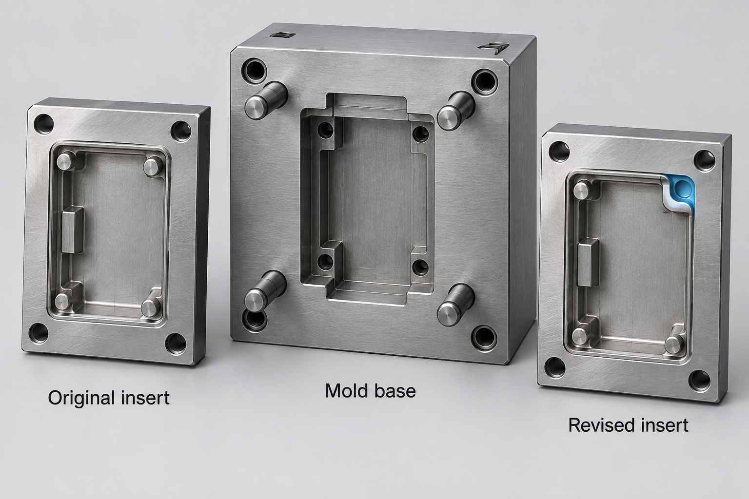
Figure 2. A revised insert can localize a modification when the mold design permits. Simplified illustration.
Ask whether insert replacement offers better durability and finish control than repeated local welding.
Do not assume an old insert can remain a usable backup. Confirm that surrounding modifications have not made it incompatible.
Review The Effects Beyond The Changed Dimension
A relocated boss or thicker wall can affect filling, cooling, ejection, and appearance.
Gate changes can alter flow behavior. New undercuts may require mechanisms that the existing tool cannot accommodate.
Review cooling passages and available steel around the proposed change. Also check machine interfaces if tool dimensions or services change.
A resin change deserves separate evaluation. It can alter shrinkage and processing behavior even when the CAD model remains unchanged.
Use the wider review described in our injection molding buyer guide before approving revised tooling.
Repair The Mold Or Replace It?
Choose the option that offers acceptable production risk and total cost over the remaining program life.
| Condition | Option Worth Investigating |
| Local wear with sound surrounding steel | Targeted repair or component replacement |
| Damage confined to a removable insert | New insert with interface verification |
| Repeated failure at the same location | Root-cause redesign rather than another identical repair |
| Extensive cracking or multiple interacting problems | Major refurbishment or replacement |
| Large design changes exceeding available tool space | New tooling or a substantially revised architecture |
| Limited remaining demand | Compare qualified repair with the actual remaining production requirement |
Tool age alone cannot make the decision. Review condition, history, expected demand, and the consequences of another interruption.
Ask for separate recommendations when a temporary recovery differs from a durable production solution.
Do not assume that any repair resets the mold’s service life. Remaining life is an engineering assessment, not a universal cycle count.
A Practical Mold Repair And Modification Workflow
A controlled workflow connects the initial evidence, authorized work, and production-release decision.
1. Record The Starting Condition
Identify the tool, cavity count, drawing revisions, and known material specifications. Photograph damage and retain representative molded samples.
Record existing repairs and unavailable information. An unknown steel grade is a planning issue that needs resolution before welding.
2. Inspect And Propose A Scope
Assess affected components and related interfaces. Describe the suspected cause, proposed method, and alternatives.
Mark the work areas on drawings or images. List any risks to cosmetic surfaces, nearby cooling circuits, or critical dimensions.
3. Approve Changes Before Irreversible Work
Confirm the target geometry, repair boundaries, finish requirements, and acceptance criteria.
For modifications, release the new CAD and drawing revisions. Avoid instructions such as “make the fit tighter” without measurable requirements.
4. Perform And Document The Work
Record component replacements and changes to the tool. Retain material and treatment records where required by the agreed scope.
Update tool drawings and spare-part information. Keep the final records consistent with the physical mold.
5. Trial And Validate The Molded Parts
Run the agreed trial using the specified resin and documented process conditions.
Check both the modified features and other characteristics that the work could affect. Include all relevant cavities.
6. Release Production And Monitor Restart
Approve samples and required reports before routine production release. Document any remaining limitations or planned follow-up checks.
Monitor the initial production run against the approved criteria. A single acceptable shot does not establish repeatable recovery.
What To Check After Mold Repair
Verify tool function and molded-part conformity before treating the repair as complete.
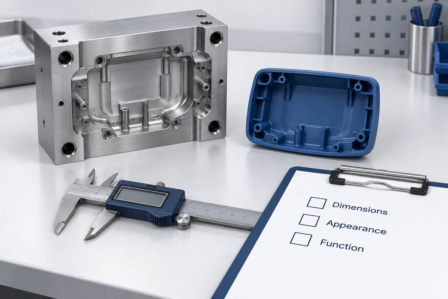
Figure 3. Sample approval should address dimensions, appearance, and function. Conceptual illustration.
| Verification Area | Evidence To Agree On |
| Tool geometry | Measurements of repaired features and critical interfaces |
| Mold operation | Suitable checks of movement, ejection, alignment, and services |
| Molded dimensions | Results against the approved drawing and conditioning requirements |
| Appearance | Samples evaluated against agreed texture, gloss, and defect standards |
| Application function | Relevant assembly, sealing, loading, or other functional tests |
| Cavity consistency | Identified samples from the relevant cavities |
| Production repeatability | Trial scope, process records, and follow-up requirements |
Define the inspection extent according to the change’s risk. A local repair can affect features beyond its immediate location.
Where automated checks are used, confirm that inspection recipes still match the revised part. Our automated inspection guide explains validation limits.
Keep a clear record linking the approved samples to the tool and drawing revisions.
What Determines Repair Cost And Turnaround?
Damage assessment, access, material condition, finishing, and validation determine the realistic quotation and schedule.
Request a breakdown covering:
- Inspection and disassembly.
- Replacement components or insert manufacture.
- Welding, machining, and any required treatment.
- Polishing, texturing, coating restoration, or fitting.
- Trial materials, machine time, and inspection reports.
- Transport, reassembly, and production restart support.
Separate workshop completion from production readiness. Sampling and approval may continue after the physical repair is finished.
Also identify scope changes that require a revised quotation. Hidden damage may become apparent only after disassembly.
Compare total recovery cost, including likely downtime and repeat-failure exposure. The lowest initial repair price may not deliver the lowest program cost.
Frequently Asked Questions
The best repair decision depends on the tool’s actual condition and the approved part requirements.
Can Every Injection Mold Be Repaired?
No. Extensive damage, unsuitable material condition, or major geometry changes can make replacement more practical.
Is Laser Welding Always Better Than TIG Welding?
No. Select the method around steel grade, repair size, geometry, and finishing requirements. Follow the applicable material guidance.
Can A Mold Be Modified To Make A Part Smaller?
Sometimes. The required steel change depends on whether the feature is formed by a cavity, core, or removable insert.
Can You Change The Resin Without Modifying The Mold?
Possibly, but evaluate shrinkage, processing, and performance first. Trials may reveal dimensions or process conditions that require further changes.
How Long Will A Repaired Mold Last?
There is no universal answer. Remaining condition, repair quality, material, operating loads, and maintenance all influence service life.
What Should You Send For A Repair Quotation?
Send current and revised drawings, mold information, defect photos, and representative sample results. Include urgency, annual volume, and remaining program life.
Discuss Mold Repairs And Modifications With TOPS
TOPS supports tooling and part review within its plastic injection molding services.
Confirm the proposed repair method, equipment needs, and validation scope after the tool information is reviewed.
Request a mold review with your tool drawings, part CAD, steel details, and repair history. Add annual volume, remaining program life, critical dimensions, finish requirements, and the required recovery date.
Conclusion
Successful mold repairs and modifications begin with diagnosis and end with verified production results. Separate restoration from design changes, review the steel and interfaces, and compare replacement options. Approve the scope before machining, then validate molded dimensions, appearance, and function before release.


