



Molded-in threads form directly in plastic during injection molding. They can remove a machining step, but require a workable release method. Your choice depends on resin, thread geometry, fit, service loads, and production volume. This guide explains how to specify, manufacture, and validate them.
What Are Molded-In Threads?
Molded-in threads are plastic thread profiles created by the mold’s cavity or core surfaces. The thread exists when the part leaves the tool.
External threads run around a shaft, neck, or connector. Internal threads run inside a cap, collar, or housing. Their helical shape can lock the molded part onto the tooling unless the release method accommodates it.
A molded-in metal insert is different. Plastic surrounds a separately manufactured insert, while the mating thread remains metal. Heat-installed inserts are another option, fitted after molding.
For your drawing, identify which construction you require. “Threaded plastic component” alone does not tell the supplier whether you want plastic threads or metal inserts.
When Should You Mold Threads Directly In Plastic?
Directly molded threads suit applications where the plastic joint meets the load, wear, and environmental requirements.
Typical candidates include closures, adjustment collars, and threaded connectors. Their suitability depends on the complete assembly, not the application name alone.
| Requirement | Direct Plastic Threads | Alternative To Evaluate |
| Stable design and recurring production | Can eliminate secondary thread cutting | Compare tooling investment against machining costs |
| Frequent screw removal | Requires wear and cycle testing | Metal insert for a more durable mating surface |
| High sustained clamp load | Creep and relaxation require evaluation | Insert plus a suitable load path or compression limiter |
| Low quantity or changing thread design | Dedicated release tooling may be difficult to justify | Secondary machining or a removable tooling core |
| Leak-tight connection | Requires a defined sealing strategy | Dedicated gasket or O-ring where appropriate |
Molding does not automatically produce a lower-cost or stronger thread. Compare the accepted assembly, including inspection, tool maintenance, and rejected parts.
How Are Molded Threads Released From The Tool?
Thread release requires splitting the tooling, rotating it, collapsing it, or deliberately deforming the part within acceptable limits.
Decide this before finalizing the thread and surrounding features. A release mechanism that fits the thread may still clash with ribs, cooling channels, or adjacent cavities.
Split Cavities For External Threads
Some external threads can sit across a mold split running along the thread axis. The cavity sections then move apart to clear the profile.
This can avoid unscrewing, but depends on part orientation and surrounding geometry. Side actions may be necessary where the main opening direction cannot provide clearance.
Specify acceptable flash and mismatch at the split. A raised seam can interfere with assembly even when the thread’s nominal diameter is correct.
Unscrewing Cores For Internal Threads
An unscrewing mechanism rotates the threaded tooling relative to the part. The mold must restrain unwanted part rotation during disengagement.
Rotation and axial movement must follow the thread lead. Lead is axial travel per revolution; it differs from pitch on multiple-start threads.
Cooling, drive space, stroke, and anti-rotation features affect the design. Unscrewing does not guarantee the shortest cycle or perfect thread quality. Vega’s threaded-core systems explanation describes coordinated rotation and retraction.
Collapsible Cores
A collapsible core reduces its effective diameter before withdrawal. This can release suitable internal undercuts without rotating the part or core.
Check the required collapse against thread depth and available space. The smallest bore, molding length, and segment arrangement constrain feasibility.
DME offers collapsible tooling capable of molding continuous circumferential thread features in suitable applications. Review its DoveTail collapsible-core documentation. Do not assume every collapsible core requires interrupted threads.
Segment witness lines and tool wear still need acceptance criteria. Request a component-specific tooling review rather than choosing by mechanism name.
Stripping Or Force Release
Stripping uses temporary part deformation to clear the threaded tooling. It is an intentional release method, distinct from thread damage during assembly.
Suitable flexible closures may support it. Feasibility depends on resin behavior at ejection, thread depth, profile, diameter, and surrounding wall flexibility.
Do not select stripping solely because the resin is PP or PE. Reinforcement, geometry, and ejection conditions can make the same material family unsuitable.
Evaluate whitening, cracking, permanent distortion, and fit after release. A successful ejection alone does not prove an acceptable thread.
Removable Hand-Loaded Cores
A removable tooling core can leave the mold with the part. An operator then disengages it outside the molding cycle.
This approach can be worth evaluating for limited quantities or development work. However, handling, core temperature, repeatability, and operator time affect production cost.
How Should You Design Molded-In Threads?
Design the thread, supporting wall, and mating component together. The thread profile cannot compensate for a weak boss or unsuitable assembly load.
Define The Mating Thread Completely
Specify nominal diameter, pitch, thread form, handedness, starts, and required engagement. Include the mating component’s drawing and material.
State the applicable thread standard and edition when interchangeability requires one. For a custom closure, provide a fully defined profile and functional acceptance criteria.
There is no universal minimum diameter for all molded plastic threads. Small-feature feasibility depends on tooling, resin, filling, and inspection capability.
Design Entry, Runout And Stops
Provide an appropriate lead-in to help the mating part start squarely. Define the thread termination and clearance near shoulders or blind-hole bottoms.
A blind thread needs adequate clearance for the mating screw. Otherwise, bottoming can crack the component before the intended joint is clamped.
Use a deliberate seating or stop feature where needed. Confirm that your assembly torque loads the intended interface.
Balance Profile And Engagement
A coarse profile can be easier to mold and less fragile in some designs. It is not automatically stronger in every joint.
Root radii can reduce stress concentration, but must remain compatible with the mating thread. Do not add arbitrary draft to a specified thread profile.
Longer engagement does not produce proportional strength gains. Load distribution, wall stiffness, and thread accuracy influence how the engaged turns share force.
Support The Thread Without Creating A Thick Mass
Review the surrounding wall and boss transitions. Large local thickness changes can create shrinkage differences, sink, and distortion.
Use supporting geometry where appropriate, while preserving the release path. A rib intended to strengthen the boss can obstruct unscrewing or stripping.
Plan Filling Around The Threaded Feature
Avoid placing gate remnants where the mating component engages. Review weld lines and incomplete filling near loaded thread roots.
Our injection molding gate guide explains how entry location affects filling and packing. Evaluate the threaded feature in that broader flow pattern.
Which Materials Work For Molded Plastic Threads?
Choose the exact resin grade from service requirements, then confirm its molding and release behavior.
The following families are starting candidates, not approved substitutions. Fillers, additives, moisture, and temperature can change their performance substantially.
| Material Family | Reason To Evaluate It | Key Check |
| PP or PE | Flexible closure designs and chemical compatibility in suitable environments | Stiffness, creep, temperature, and release deformation |
| POM | Sliding engagement and dimensional performance in suitable conditions | Chemical exposure, shrinkage, and actual wear behavior |
| PA | Tough threaded components and reinforced options | Moisture conditioning, dimensional change, and service temperature |
| PBT | Rigid engineering components and reinforced options | Grade-specific toughness, aging, and molding shrinkage |
| ABS or PC blends | Threaded features integrated into housings | Notch sensitivity, chemicals, torque, and repeated assembly |
Glass reinforcement can improve stiffness but change shrinkage and reduce deformation available during stripping. A grade suitable for unscrewing may be unsuitable for force release.
Evaluate time-dependent behavior as well as short-term strength. Plastic can creep under sustained loading, and clamp force can relax over time. Celanese discusses these effects in its polyester technical manual.
Use the selected grade’s data at the expected temperature and exposure. Room-temperature tensile strength alone does not establish thread life.
Molded Plastic Threads Or Metal Inserts?
Choose inserts when the metal mating surface offers enough service value to justify the extra component and installation requirements.
Direct plastic threads avoid a separate insert. However, their load capacity and wear remain dependent on the polymer and supporting geometry.
An insert provides metal threads, but the surrounding plastic must still retain it. It can rotate, pull out, or contribute to boss failure if the joint is poorly designed.
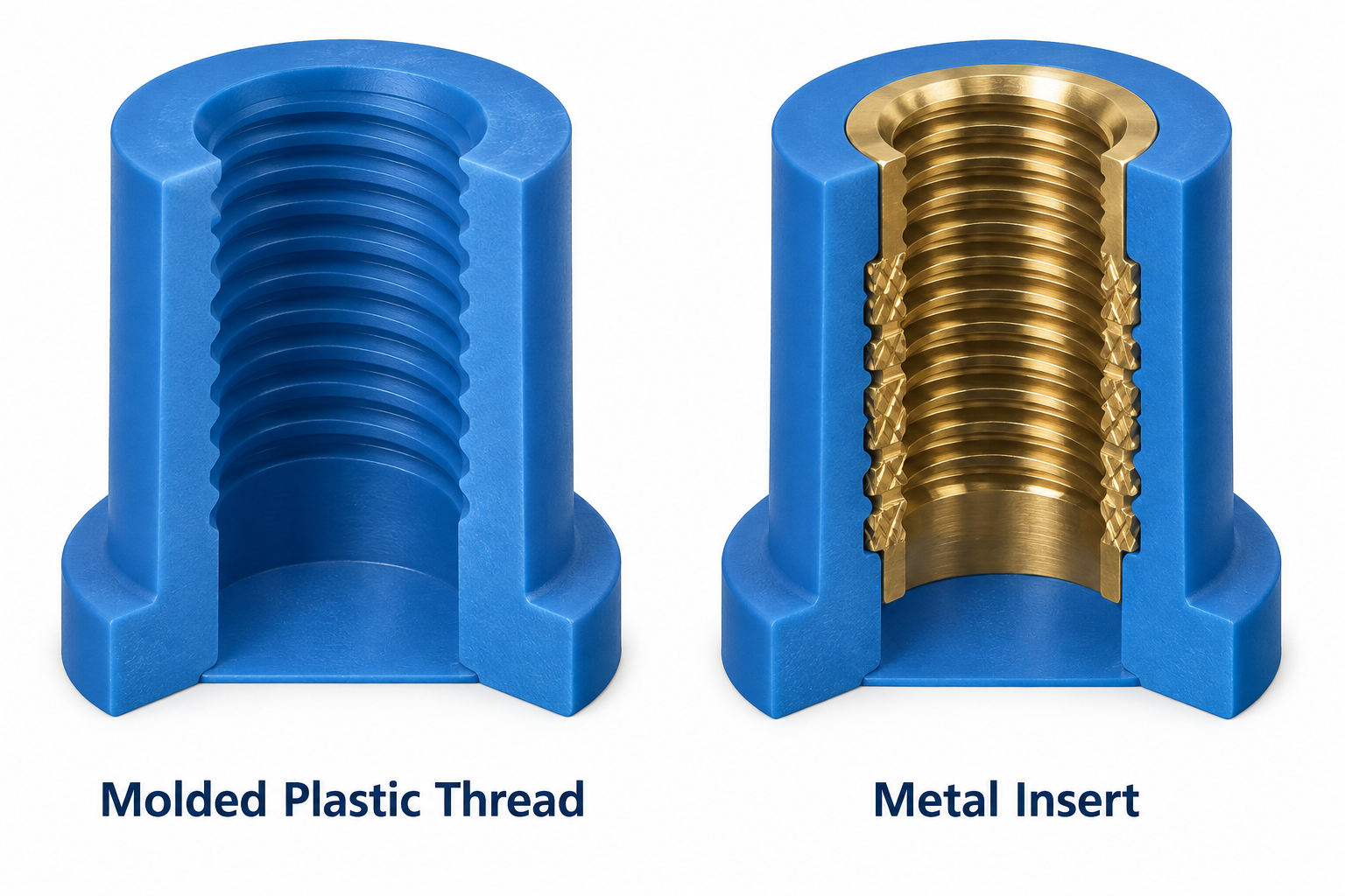
Figure 2. Direct plastic threads and an embedded metal insert use different materials at the mating surface. Conceptual cutaways.
Molded-in inserts are positioned before injection. Post-mold inserts are installed afterward using an appropriate process. They require different hole and anchoring designs.
SPIROL separates these installation methods in its threaded-inserts design guide. Follow the chosen insert supplier’s recommendations rather than reusing a hole designed for another insert type.
For a low-volume component, also compare machining the thread after molding. Include fixturing, inspection, and handling in that cost comparison.
How Do You Inspect Molded-In Threads?
Validate thread geometry and actual assembly performance under defined conditions. Visual inspection alone cannot establish fit or strength.
Separate The Mechanical Tests
Assembly torque, removal torque, and failure torque describe different events. Record each test’s purpose and method.
- Assembly torque establishes the tightening condition.
- Removal torque measures resistance when loosening the assembled joint.
- Failure torque identifies damage during an agreed destructive test.
- Axial testing evaluates separation resistance under a specified load direction.
For inserts, rotational retention within plastic is another distinct test. Avoid using “torque-out” without stating what rotates and what constitutes failure.
Check Fit And Geometry
Use appropriate thread gauges where the thread specification supports them. A plug gauge checks an internal thread; a ring gauge checks an external thread.
For custom profiles, agree on functional masters and dimensional methods. Control gauging force so the inspection does not deform the plastic or hide interference.
Inspect flash, incomplete crests, cracks, and damage from release. Check roundness and alignment where they affect assembly.
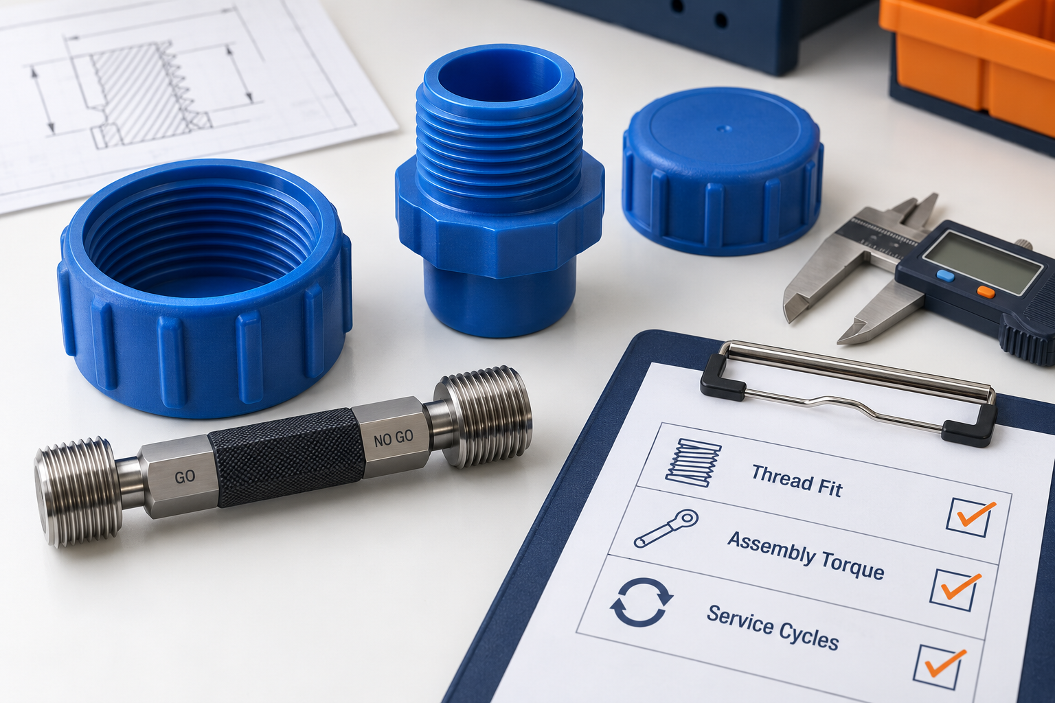
Figure 3. Thread acceptance combines fit checks and application-specific testing. Illustrative equipment, not an inspection record.
Test The Service Conditions
Define temperature, moisture conditioning, chemical exposure, and the number of assembly cycles. Test using representative mating components.
For a sealing connection, specify the sealing surface and leak-test conditions. Threads that assemble correctly do not automatically form a leak-tight joint.
Retain cavity identification and test results from a stable molding run. Recheck critical characteristics after tooling maintenance or a resin change.
What Drives The Cost Of Threaded Injection Molded Parts?
Total cost depends on tooling, release time, cavity layout, material, secondary operations, and acceptance requirements.
A complex release system increases investment and maintenance. It may still be justified when it avoids recurring manual operations at sufficient volume.
Compare quotations using the same thread definition and test requirements. Ask each supplier to identify the release method, inspection scope, and excluded operations.
Use annual demand and program life when comparing alternatives. A lower tooling price can be offset by labor, scrap, or slower production.
What Should You Send For A Manufacturing Review?
Send the part and mating-component requirements together so the supplier can assess tooling access and joint performance.
Include CAD, drawings, resin grade, thread specification, engagement, and permitted split lines. Add assembly torque, service environment, test requirements, annual volume, and program life.
TOPS lists plastic injection molding services. Confirm the proposed thread-release mechanism and validation scope for your specific project during quotation.
Request A Threaded-Part Review with your drawings, mating-part details, resin, annual volume, and acceptance requirements.
Frequently Asked Questions
These answers address common choices before you approve a molded-thread design.
Can Internal Threads Be Injection Molded?
Yes. Unscrewing, collapsible tooling, removable cores, or suitable stripping designs can form and release them. The correct approach depends on geometry, resin, and production requirements.
Do All External Threads Need An Unscrewing Mold?
No. Some can release through split cavities or side actions. Check part orientation and nearby features before assuming a simple split will work.
Are Molded-In Threads The Same As Molded-In Inserts?
No. Molded-in threads are plastic features. Molded-in inserts are separate components, commonly metal, embedded during molding.
Can You Strip Threads In Glass-Filled Plastic?
Do not assume that you can. Reinforcement can limit permissible deformation. Have the supplier evaluate the exact grade and geometry, including damage after release.
Do Molded Threads Need A Universal Minimum Diameter?
No single minimum applies to every design. Ask for a grade-specific tooling and inspection review rather than applying an unsupported diameter rule.
Can Plastic Threads Replace Metal Threads?
Sometimes, when load, wear, temperature, and assembly requirements permit. Validate the complete joint. Metal-thread strength alone also does not establish an insert’s retention in plastic.
Conclusion
Choose molded-in threads by evaluating service loads and release feasibility together. Specify the mating geometry, resin, inspection conditions, and expected life. Then compare direct plastic threads, inserts, and machining on total cost. Approve production only after fit and functional testing support the selected design.


