Diseñar una pieza de plástico robusta que pueda fabricarse de manera consistente y rentable, un proceso conocido como Diseño para la Manufacturabilidad. (DFM)—requires a holistic view that integrates material science, tooling engineering, and production constraints. Successful DFM focuses on fulfilling the functional intent of the part while proactively eliminating risks related to material defects, debilidades estructurales, and complex molding cycles.
Here is an in-depth exploration of eight essential factors to consider to ensure a successful production process.

Diseño de piezas de plástico para su fabricación
1. Consideraciones materiales
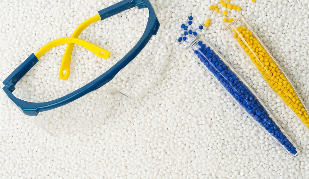
The resin selection is arguably the single most impactful decision in plastic part design. Simply choosing a familiar grade is inadequate; the material must be optimized for the end-use environment and manufacturing process.
| Consideración | Detail for Manufacturability |
| Temperatura | Determine the Heat Deflection Temperature (HDT) and Vicat softening point. High thermal stress (p.ej., prolonged exposure or rapid temperature changes) requires materials with high thermal stability to prevent softening or creep failure. |
| Resistencia química | Evaluate potential contact with solvents, aceites, and cleaning agents. Chemical incompatibility can lead to stress cracking, swelling, or degradation, compromising the part’s long-term integrity. |
| Agency Approvals | Verify compliance with specific regulatory standards (p.ej., UL ratings for flammability, FDA/ISO standards for medical or food contact). Non-compliance requires costly material changes later. |
| Asamblea | The material must be compatible with assembly methods such as ultrasonic welding, solvent bonding, snap-fit features, or mechanical fasteners. Baja fricción materials like Acetal (POM) are preferred for moving parts. |
| Finalizar | The resin’s inherent properties and color consistency must meet cosmetic requirements (p.ej., gloss level, texture standards like MT or SPI finishes) as molded, minimizing secondary operations. |
| Costo & Disponibilidad | Beyond the resin price, consider the material’s impact on Tiempo de ciclo (slower cooling materials increase cost). Ensure the required volume is consistently available from suppliers to mitigate supply chain risk. |
2. Radius and Corner Transitions
Sharp internal corners are prime locations for structural failure due to stress concentration. When a load is applied, the force is focused at the apex of a sharp corner, leading to premature cracking.
Radio interno (Filetes): Radii should be incorporated at all internal corners. The internal radius $(R)$ should ideally be equal to or greater than $50\%$ del grosor nominal de la pared $(t)$ to minimize stress, es decir., $R \ge 0.5T$.
Corner Thickness Rule: To avoid the formation of thick, cooling-prone areas at corners, the thickness at the corner should be maintained in a narrow range. A common guideline is to keep the resulting corner thickness between $0.9 \times T$ y $1.2 \times T$ of the nominal wall thickness. This ensures uniform cooling behavior.
3. Wall Thickness Consistency
Maintaining a uniform wall thickness across the entire part is the most critical rule in DFM. Inconsistent thickness leads to a host of defects during molding:
Inconsistent Flow: Melted plastic follows the path of least resistance. If a thick section precedes a thin section, the thicker area may fill first, causa calentamiento por cizalla in the thin area or failing to fill it completely (tiros cortos).
Cooling Rate Discrepancy: Thicker areas require significantly longer to cool than thinner areas. This disparity in cooling time creates thermal stress between sections.
Defects: Non-uniform cooling causes differential shrinkage, which manifests as:
Marcas de fregadero: Depression on the surface opposite a thick section due to material pulling inward as the core cools.
Voids: Trapped gas or vacuum bubbles deep within a thick section.
Deformación: Distortion of the part as internal stresses are released upon ejection.
4. Ubicación de la puerta
The gate—the small opening connecting the runner system to the part cavity—is where pressure transmission and material flow control originate. Its placement dictates the filling pattern and the final quality.
Ideal Placement: Gates should ideally be placed at the sección más gruesa of the part to ensure the material can be packed efficiently into the thinner sections downstream.
Estética: The gate location also determines the location of the gate vestige (the mark left when the runner is removed). Placement should minimize cosmetic impact.
Gate Types: Different gate types control flow and shear:
Pin Gates: Used for multi-cavity molds; offer automatic degating but create high shear.
Submarine Gates: Allow automatic degating below the part surface; require a small radius at the gate area.
Hot Tip Gates: Used in hot runner systems; offer efficient filling and minimal waste.
5. Draft
Draft is the essential taper applied to the vertical walls of a plastic part to facilitate its release from the mold core or cavity.
Mecanismo: Without draft, the friction between the solidified part and the mold surface, combined with the vacuum created upon separation, can prevent ejection or cause drag marks.
Standard Requirement: A minimum draft angle of $1^\circ$ a $2^\circ$ is typically required for smooth vertical walls.
Textured Surfaces: If the mold surface has a texture (which creates more friction), the draft angle must be increased, often to $3^\circ$ or $5^\circ$ per side, depending on the depth of the texture.
Ejection Failure: Insufficient draft can result in excessive stress on the ejector pins, conduciendo a pin push marks or damaging the mold steel.
6. Inclusion of Ribs
Las costillas son delgadas, wall-like projections used to increase the bending stiffness and structural strength of a plastic part without substantially increasing the overall wall mass, thereby maintaining a shorter cycle time.
Reinforcement: Ribs effectively channel stresses and prevent flexing in parts designed with minimal nominal wall thickness.
Sink Mark Prevention: The thickness of the rib must be carefully managed to prevent the formation of sink marks on the opposite, visible surface of the part.
Rib-to-Wall Ratio: To avoid creating a hot spot that cools slowly and pulls the surface inward, the rib thickness should be limited to between $50\%$ y $70\%$ (commonly $60\%$) of the adjoining nominal wall thickness $(t)$. If a thicker rib is required for strength, the designer must core out the base material to reduce the mass and promote uniform cooling.
7. Mold Shrinkage
All plastics shrink as they cool from the melt temperature to the ambient temperature. This volumetric reduction must be accounted for in the mold design, not the part design itself.
Crystalline vs. Amorfo:
Crystalline/Semi-Crystalline Materials (p.ej., PÁGINAS, EDUCACIÓN FÍSICA): Exhibit higher and more variable shrinkage (arriba a $20\%$ by volume). They are prone to anisotropic shrinkage (shrinking more in the direction of flow).
Amorphous Materials (p.ej., abdominales, PD): Exhibit lower and more predictable shrinkage (isotropic).
Shrinkage Compensation Strategies:
Tool Design Adjustment: The most common solution is applying a shrinkage allowance factor when machining the mold cavity.
Processing Optimization: Adjusting the packing pressure y hold time allows more material to be crammed into the cavity, compensating for shrinkage and minimizing voids.
Formulation Adjustment: Adding fillers (such as glass fibers or minerals) can significantly reduce the material’s thermal shrinkage rate.
8. Special Features (Undercuts and Side Actions)
Features that prohibit the part from being stripped perpendicular to the mold’s opening direction are known as undercuts (p.ej., side holes, latching features, and external threads). They require moving mold components.
Requirement for Side Actions: When an undercut exists, side actions (also called slides, moving cores, or hydraulic pulls) must be integrated into the tooling.
Mecanismo: Side actions move in a direction lateral to the mold opening axis. They form the undercut feature and must retract before the mold begins to separate, clearing the interference.
Cost and Complexity: Incorporating side actions adds substantial cost, as they require dedicated hydraulic or mechanical activation, precision guiding components, and increase mold maintenance and setup complexity. Working closely with an experienced molder is vital to determine if the cost of the side action is justified by the functional necessity of the feature.
Conclusión
A successful plastic injection molding project is forged in the design phase. By rigorously applying these eight DFM factors—from selecting the optimal resin based on thermal and chemical demands to correctly managing thickness transitions, radius, and draft—designers can mitigate common production risks. Partnering with a knowledgeable plastics engineer ensures that the functional requirements of the part are met while simultaneously achieving the highest possible quality at the lowest manufacturing cost, accelerating the product’s journey to market. Contáctenos para más información.


