



Laser marking specifications should define the content, emplacement, état de surface, and acceptance method for your CNC parts. A dark mark alone does not establish traceability or durability. Agree the marking process and sample approval before production, especially when the part has protective finishes or functional surfaces.
Define The Mark Content Before Selecting The Process
Your marking specification should distinguish fixed identification, variable production data, and any machine-readable symbol.
State the exact part number and revision format. Decide whether you need a batch identifier, an individual serial number, ou les deux.
Specify who supplies the variable data and who controls serial allocation. Define how the supplier handles duplicate numbers, scrapped parts, and rework.
A visible identifier provides a link to records. It does not establish the material history without those records.
For material documentation, notre material certificate guide explains the stock-to-part evidence chain. Keep that chain connected to the delivered marking and shipment records.
Distinguish Engraving From Surface Color Changes
Laser marking covers different surface interactions, so you should specify the required result rather than assuming one process.
TRUMPF’s laser marking overview distinguishes procedures including engraving and annealing. Engraving removes material and creates a recess.
En revanche, c'est annealing explanation describes color formation through a surface oxide film. A color mark should not be specified as a recessed engraving.
| Marking Requirement | Informations pour accepter |
|---|---|
| Recessed identification | Permitted depth, remaining section, edge condition, et méthode d'inspection |
| Surface contrast | Approved appearance, état de surface, and durability requirements |
| Marking through a coating | Whether coating removal is permitted and how protection is assessed |
| Machine-readable identification | Data format, symbol requirements, reading conditions, and verification criteria |
Do not treat these outcomes as interchangeable. Ask the specialist to propose a process for your actual metal, finition, and service environment.
Locate The Mark Without Compromising Functional Surfaces
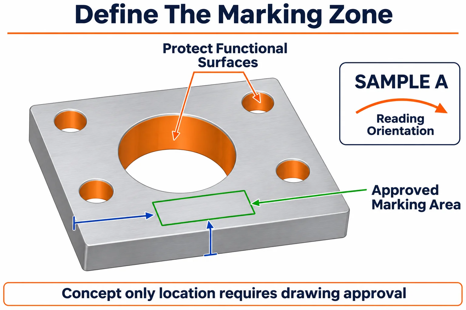
You should define an approved marking zone relative to drawing features and protect surfaces that must remain unchanged.
Show the location, orientation, and maximum envelope on the drawing. Include the reading direction after assembly when access matters.
Identify sealing lands, bearing seats, fils de discussion, sections minces, and cosmetic faces requiring protection. Any proposed marking on them needs engineering approval.
Avoid leaving the location to a general instruction such as “mark where convenient.” A suitable visible area may become hidden after installation.
For cylindrical parts, review curvature and viewing access with the marking supplier. Verify the proposed layout on representative geometry.
Approve The Mark On The Final Surface Condition
Your approval sample should represent the actual material, finition, and operation sequence of the delivered part.
State whether marking occurs before or after anodizing, placage, passivation, enrobage, or final cleaning. Approve any change to that sequence.
Ask whether the proposed process removes a coating or changes the metal surface. Define any required corrosion, porter, or cleaning evaluation separately.
A photograph can establish an appearance reference under agreed conditions. It cannot establish resistance to chemicals, abrasion, or the full service environment.
Retain the sample identity and processing route. Review changes in alloy, finition, marking settings, or subcontractor against the approved requirements.
Separate Code Reading From Symbol Verification
A successful scan confirms that one reader decoded the symbol under those conditions; verification evaluates specified symbol quality.
If you request a code, define the symbology and data structure. Data Matrix and GS1 DataMatrix should not be treated as interchangeable instructions.
GS1’s DataMatrix guideline discusses symbol structure, clear surrounding space, marking technology, and direct-part-mark evaluation. Apply the requirements relevant to your identification system.
Specify available marking space before compressing the content. Review symbol size, surrounding clear space, texture de la surface, curvature, and lighting together.
For GS1 DataMatrix, GS1’s verification guidance calls for an ISO/IEC-compliant verifier. Agree the applicable method, grade, installation, and report format before acceptance.
Also test the intended production reader where practical. Keep reader performance and formal verification requirements distinct in the order.
Control Production Data And Acceptance Records
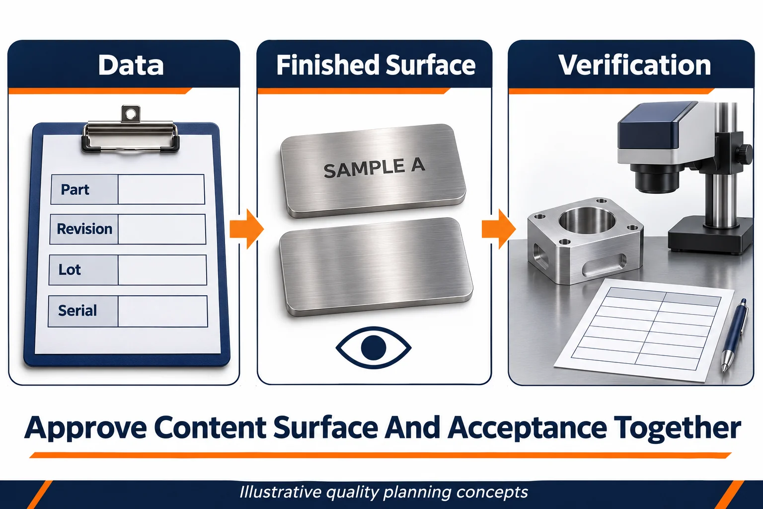
Your release plan should check identification accuracy as well as the physical quality of the mark.
Approve the artwork and variable-data rules before the first production batch. Include part revision, font, orientation, and permitted abbreviations.
Define the required inspection coverage. Record which checks cover content, emplacement, physical condition, code quality, and record linkage.
| Acceptance Check | Preuve à conserver |
|---|---|
| Correct content | Approved artwork and comparison with the released data |
| Correct location | Drawing zone, orientation, and dimensional check where required |
| Acceptable surface | Approved sample and required functional or durability evaluations |
| Readable symbol | Reader test and verification report when specified |
| Traceable delivery | Marked identities linked to accepted quantities and shipment records |
Define the disposition for missing, incorrect, or duplicate marks. Do not remark or erase identification without an approved rework route.
Compare Quotes With The Same Marking Scope
Your quote should separate part manufacture, marking setup, variable-data handling, approbation de l'échantillon, and verification requirements.
TOPS fournit Services d'usinage CNC. Send the marking requirements with the component drawing so the complete delivery scope can be reviewed.
Confirm who performs marking and who retains its records. Resolve any proposed outside processing before approving the order.
Costs depend on material, finition, accéder, montage, data changes, quantités, and inspection scope. A decorative logo and serialized verified symbols involve different work.
Questions fréquemment posées
You should resolve identification and acceptance questions before releasing a marked CNC part order.
Is Laser Marking Always An Engraving
Non. Some procedures remove material, while others change surface appearance. Specify the required outcome and permitted surface change.
Does A Serial Number Prove Material Traceability
Non. It needs a controlled link to material, production, inspection, and delivery records appropriate to your order.
Can A Phone Scan Replace Code Verification
Not when formal verification is required. A phone scan does not establish the specified quality grade and measurement conditions.
Should Marking Always Follow Surface Treatment
There is no universal sequence. Approve the route against appearance, protection, readability, and service requirements.
Can The Supplier Choose Any Free Surface
Only if the drawing permits it. Specify an approved area and protect functional surfaces from unintended alteration.
What Should A Marking RFQ Include
Envoyez le dessin, matériel, finition, quantité, artwork, variable-data rules, marking zone, besoins de durabilité, et conditions d'acceptation.
Request A CNC Part Marking Review
Contactez-nous with your part files, matériel, finition, quantités, and marking specification. Include the data rules and required acceptance evidence. Agree the sample and processing sequence before production approval.