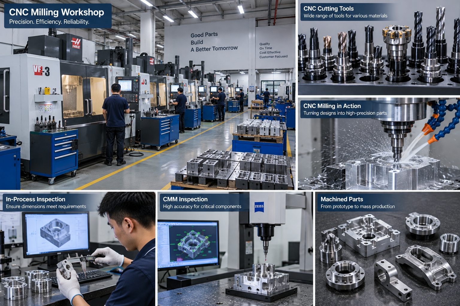



CNC milling tools remove material to create slots, pockets, contours, holes, and finished faces. The right cutter controls quality, cycle time, and cost. This guide covers the main tool types, materials, coatings, and how to choose each one.
What Are CNC Milling Tools?
CNC milling tools are rotating cutters that machine material from a workpiece.
Each tool has a specific shape for a specific feature. Choosing correctly avoids rework, chatter, and broken tools. Tool choice depends on the operation, material, geometry, and machine.
Common Cutting Tools Used On CNC Milling Machines
A CNC mill tool magazine holds more than milling cutters. It also carries drills, reamers, and thread tools.
| Tool | Primary Use |
| End mill | Slots, pockets, profiling |
| Ball nose end mill | 3D contours and curved surfaces |
| Bull nose / corner-radius end mill | Flat floors with radiused corners |
| Face mill | Large flat surfaces |
| Drill | Holes |
| Reamer | Accurate finished holes |
| Thread mill | Threads |
| Chamfer mill | Angled edges |
| Dovetail cutter | Undercuts and slides |
| T-slot cutter | T-shaped clamping slots |
| Keyseat cutter | Keyways |
| Angle cutter | V grooves and serrations |
| Form cutter | Repeated special profiles |
End Mills And Their Uses
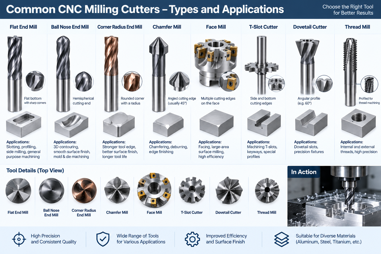
End mills are the most common milling tools. They cut on the periphery and, for center-cutting types, on the end.
- Flat end mills cut square-bottom slots and pockets.
- Ball nose end mills cut 3D contours and curved surfaces. On 3D surfaces, cutter diameter and stepover determine scallop height. A smaller stepover improves finish but increases cycle time.
- Bull nose / corner-radius end mills give flat floors with a radiused corner.
- Roughing end mills remove material fast with a serrated edge.
- Center-cutting end mills plunge; non-center-cutting types do not.
See all things about end milling for more detail.
Face Mills
Face mills machine large flat surfaces with multiple cutting edges.
They give a good finish and remove material quickly across a wide area. Many face mills are built around replaceable inserts. They are common for squaring stock and finishing flat faces. Read a complete overview of face milling.
Drilling And Hole-Making Tools
Drills create holes. Reamers and other tools refine them.
- Twist drills make standard holes.
- Micro drills make very small holes and need controlled runout.
- Reamers bring a hole to a precise size and finish.
- Spot drills start a hole accurately.
Hole depth, diameter, and material decide the tool and method. See deep hole drilling when depth is large.
Threading Tools
Threads can be cut with taps or thread mills.
Tapping is fast and efficient for a specific thread size, but a broken tap can be difficult to remove, particularly in blind holes or difficult materials. Thread mills can produce internal or external threads, offer good control of thread size, and are useful for larger threads, difficult materials, or applications where reducing the risk of a broken tap matters. Compare thread milling vs tapping.
Specialty Milling Cutters
Specialty tools cut shapes that standard end mills cannot reach.
- Chamfer mills make bevels and deburr edges.
- Dovetail cutters cut undercuts for slides and fixtures.
- T-slot cutters make clamping slots.
- Keyseat and Woodruff cutters cut shaft keyways.
- Angle cutters make V grooves and serrations.
- Form cutters reproduce a profile in one pass.
- Fly cutters use a single edge for broad flat surfaces in suitable setups, though indexable face mills are more common in production.
For profile copying, see form milling essentials.
Solid Carbide Vs Indexable Milling Tools
Milling tools are either solid or built around replaceable inserts.
| Tool Type | Best For | Main Advantage | Limitation |
| Solid carbide | Smaller diameters, detailed features, finishing | Rigidity and precision | Whole tool replaced when worn |
| Indexable cutter | Larger diameters, face milling, heavy roughing | Replaceable cutting edges | Larger minimum tool size |
| Brazed or tipped tool | Specialized applications | Combines substrate and cutting material | Less common for general CNC milling |
Roughing Vs Finishing Cutters
Roughing and finishing put different demands on the tool.
- Roughing: high material removal, stronger edges, large chip clearance, and secondary surface finish.
- Finishing: low stock allowance, sharp and stable edges, controlled runout, and prioritized finish and accuracy.
A roughing pass removes stock. A finishing pass controls size and surface.
Milling Tool Materials
Tool material sets hardness, toughness, and cutting speed.
| Tool Material | Typical Use |
| High-speed steel (HSS) | Lower-speed work, interrupted or less rigid conditions, toughness, low tooling cost |
| Solid carbide | Higher speeds, production, rigidity, wear resistance |
| Cermet | High-speed finishing of steels and selected cast materials |
| CBN | Hardened steel, often as inserts or tipped edges |
| PCD | Non-ferrous and abrasive materials, often as inserts or tipped edges |
CBN and PCD are premium superhard materials used for specialized applications, often as inserts or tipped cutting edges rather than general-purpose end mills. PCD is generally used for non-ferrous and abrasive materials, not steels.
Milling Tool Coatings
Coatings reduce wear and heat at the cutting edge.
| Coating | Typical Application |
| TiN | General-purpose machining |
| TiCN | Abrasion resistance at moderate cutting temperatures |
| TiAlN / AlTiN | Steel, stainless, titanium, high-temperature cutting |
| AlCrN | Difficult materials and high-temperature or wear conditions |
| CrN | Non-ferrous applications, resistance to built-up edge |
| DLC | Low-friction cutting of selected non-ferrous materials |
Coating selection depends on the tool substrate, workpiece material, cutting speed, coolant strategy, and cutter geometry. Advanced coatings only deliver their benefit when cutting parameters are appropriate.
For aluminum, sharp polished carbide tools, often uncoated or coated for non-ferrous work, are common because they reduce built-up edge and improve chip evacuation.
Milling Tool Geometry
Geometry controls cutting action, finish, and tool life.
- Flute count: fewer flutes give larger chip gullets and suit difficult chip evacuation. More flutes increase edge engagement and core rigidity and can support higher feed rates, but leave less chip space. Finish depends on geometry, feed per tooth, runout, rigidity, material, and conditions, not flute count alone.
- Helix angle: affects axial force, chip evacuation, edge engagement, and finish. Higher-helix tools can cut more smoothly in many finishing and non-ferrous applications. Lower or specialized helix geometries may suit rigidity or difficult materials.
- Tool diameter: use the largest cutter that can access the feature while meeting the required corner radius.
- Flute length and overhang: keep flute length sufficient but not excessive. Shorter overhang improves rigidity and reduces deflection.
- Length-to-diameter ratio: long slender tools deflect more and usually need lighter cutting.
- Axial depth of cut (Ap) controls engagement along the tool axis. Radial width of cut (Ae) controls side engagement. Both affect force, heat, chip thickness, deflection, and tool life.
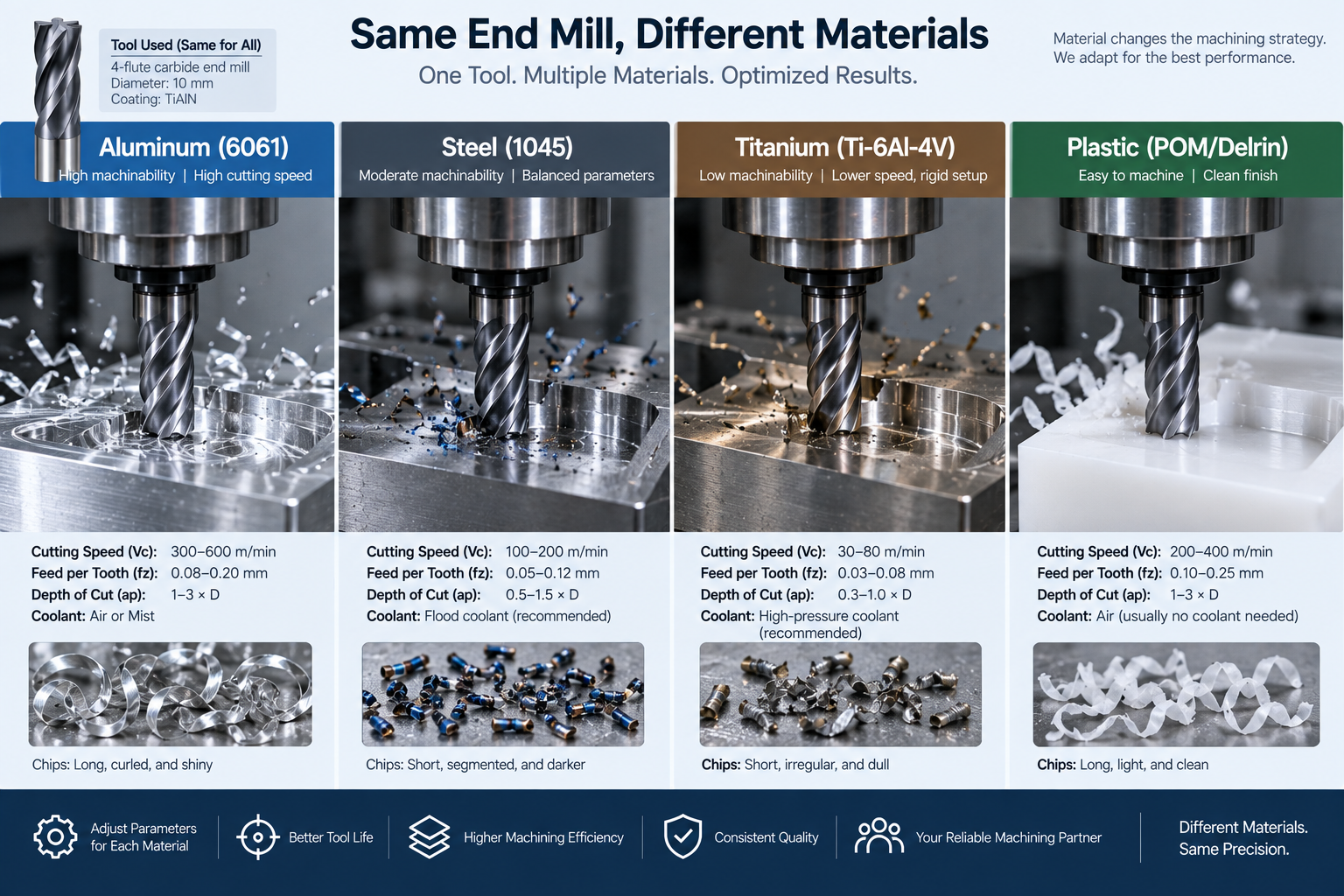
Which Milling Tools Work Best For Different Materials?
| Workpiece | Typical Starting Approach |
| Aluminum | Sharp carbide, large chip space, polished or non-ferrous geometry |
| Mild or alloy steel | Carbide with a material-appropriate coating |
| Stainless steel | Tough carbide geometry, controlled chip load, heat-resistant coating |
| Titanium | Rigid carbide, controlled engagement, strong heat management |
| Hardened steel | Specialized carbide or CBN depending on hardness and application |
| Plastics | Sharp edges and geometry that limits heat and burring |
How To Choose A Milling Tool
| Feature Or Operation | Recommended Tool |
| Flat slot or pocket | Flat end mill |
| 3D contour | Ball nose end mill |
| Flat floor with radiused corner | Bull nose / corner-radius end mill |
| Large flat face | Face mill |
| Standard hole | Twist drill |
| Accurate hole | Drill then ream |
| Thread | Thread mill or tap |
| Chamfer | Chamfer mill |
| Dovetail undercut | Dovetail cutter |
| Keyway | Keyseat cutter |
| Repeated profile | Form cutter |
After choosing the cutter type, confirm cutter diameter, corner radius, flute length, tool reach, holder clearance, and required overhang. The correct shape is not enough if the holder cannot access the feature or the tool becomes too flexible at the required reach.
Toolholding, Runout, And Tool Reach
A good tool needs a good holder.
- General collet holders provide flexibility across many tool sizes.
- Hydraulic and shrink-fit holders can give high concentricity and suit low-runout, stable high-speed cutting.
- At high spindle speeds, holder balance and runout become increasingly important for tool life, accuracy, and finish.
- Keep overhang short to reduce deflection and chatter.
Speeds, Feeds, And Tool Life
Speeds and feeds depend on tool, material, machine, coating, and conditions.
- Feed per tooth, or chip load, matters. Feeding too lightly causes rubbing. Excessive chip load overloads the edge.
- Use the tool manufacturer recommended starting data, then adjust for your machine and setup.
- Coolant and chip evacuation prevent heat damage.
- Cutting direction affects engagement, finish, and backlash sensitivity. See climb milling vs conventional milling.
- Monitor wear and replace tools before they break.
Frequently Asked Questions
What is the best tool for a flat-bottom pocket?
A flat or square end mill.
What is the difference between a ball nose and flat end mill?
A ball nose cuts curved 3D contours. A flat end mill cuts square slots and flat floors.
Can a CNC milling machine cut threads?
Yes. CNC mills can produce threads using a thread mill, and internal threads can also be cut with taps where appropriate. Thread milling uses a dedicated cutter following a helical toolpath.
What is the difference between solid carbide and indexable milling tools?
Solid carbide tools are precise but replaced whole when worn. Indexable tools use replaceable inserts and suit larger or heavier cuts.
Why do end mills break?
Common causes are runout, wrong feeds, deep cuts, poor chip evacuation, chip recutting, and a brittle tool for the job.
How do I reduce chatter in milling?
Use a rigid setup, shorten overhang, adjust speed and feed, check runout, reduce radial engagement, or change spindle speed to move away from an unstable condition.
What is feed per tooth?
It is the chip load removed by each cutting edge per revolution. It must match the tool and material.
Get CNC Machining Guidance
Send your 3D model, 2D drawing, material, quantity, tolerances, and surface-finish requirements. Our engineers will select the machining strategy, cutter type, tooling, and inspection approach based on the part.