



Multi-slide die casting vs conventional die casting is primarily a tooling and machine-layout comparison. Your choice depends on alloy, geometry, tolerances, and production volume. Multi-slide deserves consideration for small, intricate parts. Conventional die casting covers a broader range of sizes and can also produce complex features.
What Is The Main Difference?
Multi-slide die casting forms the cavity with several moving die blocks; conventional tooling uses two main die halves.
In a multi-slide system, coordinated slides approach and withdraw from different directions. Conventional tooling opens along its main axis, with additional core movements when required.
Conventional die casting can also use slides. NADCA describes production dies incorporating multiple cavities and movable cores for complex features. Having side actions does not automatically make a conventional machine a dedicated multi-slide system. NADCA Tooling Guidance
For your project, compare the proposed tooling layouts rather than counting slides alone.
| Factor | Multi-Slide Die Casting | Conventional Die Casting |
| Tool Layout | Multiple coordinated die blocks | Two main halves, with optional core slides |
| Common Starting Point | Small components with features facing several directions | Components across a broader size range |
| Material Route | Often zinc; magnesium requires suitable equipment | Zinc, aluminum, or magnesium with suitable equipment |
| Complex Features | Several withdrawal directions can support intricate geometry | Core slides can form side features and undercuts |
| Dimensional Accuracy | Must be validated for the specific features | Must be validated for the specific features |
| Secondary Machining | May decrease when features can be cast directly | May also decrease through effective core design |
| Tooling Cost | Depends on the complete tool and machine arrangement | Depends on cavities, cores, size, and tool requirements |
| Production Economics | Attractive when geometry and output suit the system | Attractive when capacity and tooling suit the project |
Neither process wins every category. You need a comparison based on the same drawing and acceptance requirements.
How Do The Two Processes Work?
Both processes inject molten metal into reusable steel tooling, but their opening and release sequences differ.
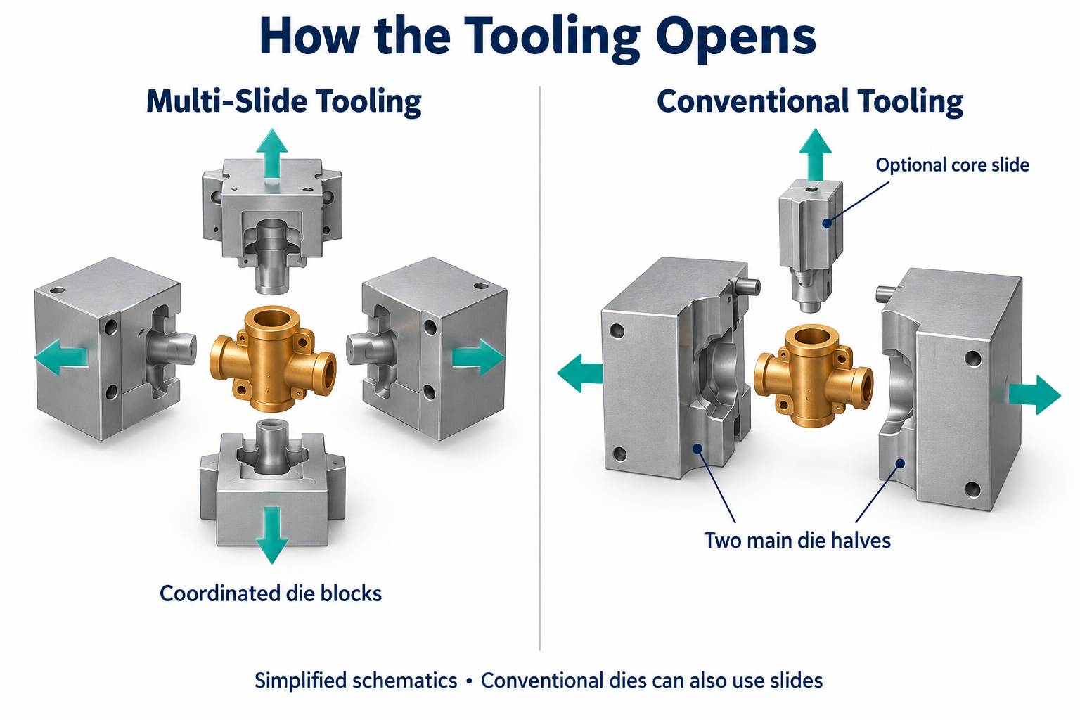
Multi-slide tooling compared with conventional die halves and an optional core slide
Multi-Slide Die Casting
A typical sequence includes:
- Die blocks move together and close the cavity.
- The injection system fills the cavity with molten alloy.
- The metal solidifies.
- Slides withdraw in the required sequence.
- The casting separates from the tooling and proceeds to downstream operations.
Machine configurations vary. Techmire describes systems with four to six slides, including arrangements supporting automatic runner separation.
These capabilities can reduce handling and secondary work when your geometry suits the tooling. They do not mean every component leaves the machine ready for assembly. Techmire Technology
Conventional Die Casting
Conventional tooling closes its fixed and moving halves before injection. Any movable cores enter their required positions.
After solidification, the cores retract as needed. The die opens, and the casting is ejected.
Gate removal, deburring, machining, and finishing follow according to your drawing. A suitable conventional tool can cast features that would otherwise require machining.
Multi-Slide Is Different From Multi-Cavity
“Multi-slide” describes tooling movement. “Multi-cavity” describes how many part cavities a die contains.
A multi-slide tool may produce several components per shot. Conventional tooling can also use multiple cavities.
When comparing output, ask for both the cavity count and the complete production cycle. Techmire Machine Configurations
Which Materials Suit Each Process?
Your alloy requirements narrow the process choice before tooling geometry does.
Multi-slide and conventional describe tool arrangements. Hot-chamber and cold-chamber describe how metal enters the die.
These classifications should not be treated as interchangeable.
Zinc
Zinc is an important candidate when you need intricate details, dimensional consistency, or decorative finishing.
NADCA identifies complex shapes, tight tolerances, and plating suitability among zinc die casting’s advantages. Those benefits apply to the alloy and process combination, rather than exclusively to multi-slide tooling. NADCA Zinc Die Castings
For a zinc component, compare both tool layouts if both can meet your requirements.
You can also review our zinc die casting services when preparing your project requirements.
Aluminum
Conventional cold-chamber die casting is a common starting point for aluminum components.
The metal is melted separately and transferred into the injection sleeve. A plunger then forces it into the closed die. NADCA Cold-Chamber Process
Do not assume a multi-slide machine designed for zinc can process your specified aluminum alloy.
Magnesium
Magnesium can be processed using suitable die casting equipment, including specialized multi-slide systems.
Techmire lists magnesium machines separately from its zinc and lead equipment. Confirm the supplier’s actual machine and alloy compatibility. Techmire Products
For either tooling route, identify the alloy grade on your drawing. “Zinc,” “aluminum,” or “magnesium” alone is insufficient for a production specification.
Which Process Offers Better Tolerances And Surface Finish?
Neither process has one universal tolerance or surface-finish value.
A published capability number means little unless it refers to a comparable alloy, dimension, geometry, and inspection method.
NADCA’s product standards address standard tolerances, precision tolerances, geometric dimensioning, and miniature die casting separately. This is more useful than assigning one accuracy figure to an entire process. NADCA Product Specifications
For your critical dimensions, ask:
- Which features come from the same tooling element?
- Which dimensions cross a parting line or slide interface?
- Which surfaces establish the inspection datums?
- Are requirements measured before or after finishing?
- Which features require machining?
Parting-line placement matters because it affects how the tool forms your component. Review that location before approving the die concept. NADCA Parting-Line Guidance
For cosmetic surfaces, mark the visible areas on your drawing. Agree on acceptable gate marks, parting lines, and ejector marks.
If your component requires plating, painting, or polishing, include those operations in the comparison. A visually attractive raw casting may still require substantial finishing.
Which Process Has The Lower Total Cost?
The lower-cost process is the one that delivers accepted finished parts at the lowest total program cost.
A lower tooling quote does not necessarily produce a lower finished-part price.
For a practical comparison, use:
Cost Per Accepted Part = Total Agreed Program Cost ÷ Accepted Parts Delivered
Include tooling, casting, trimming, machining, finishing, inspection, and agreed maintenance costs. Apply the same packaging and delivery assumptions to both quotations.
Tooling Investment And Program Volume
Do not assume multi-slide tooling always costs more.
A conventional design with several core mechanisms may be more involved than a suitable multi-slide arrangement. A straightforward conventional tool may also be the more economical solution.
Request tooling quotations against the same drawing revision, cavity assumptions, and expected program volume.
NADCA identifies tool steel, thermal loading, and erosion among tooling cost factors. Production quantity and reduced secondary work also affect the economics. NADCA Tooling Costs
Production Rate
Compare accepted output per hour instead of advertised machine speed.
A useful planning relationship is:
Accepted Output = Shots Per Hour × Parts Per Shot × Yield
Then account for downtime when estimating scheduled capacity.
Machine specifications may quote dry-cycle speed. That figure does not include every step required to cast, cool, and handle your actual component.
Solidification time and moving-tool sequences also affect the production cycle. NADCA Process Costs
Secondary Operations
A process becomes more attractive when it removes an expensive downstream operation.
However, both routes may still need machining for specified interfaces, threads, or finished dimensions. NADCA distinguishes components needing only trimming from those requiring further processing. NADCA Secondary Processing
Ask the supplier to identify every operation included in the unit price. For more quotation factors, see our die casting tooling cost guide.
When Should You Choose Each Process?
Evaluate multi-slide when several withdrawal directions could simplify a small component; evaluate conventional tooling when its capacity better fits your project.
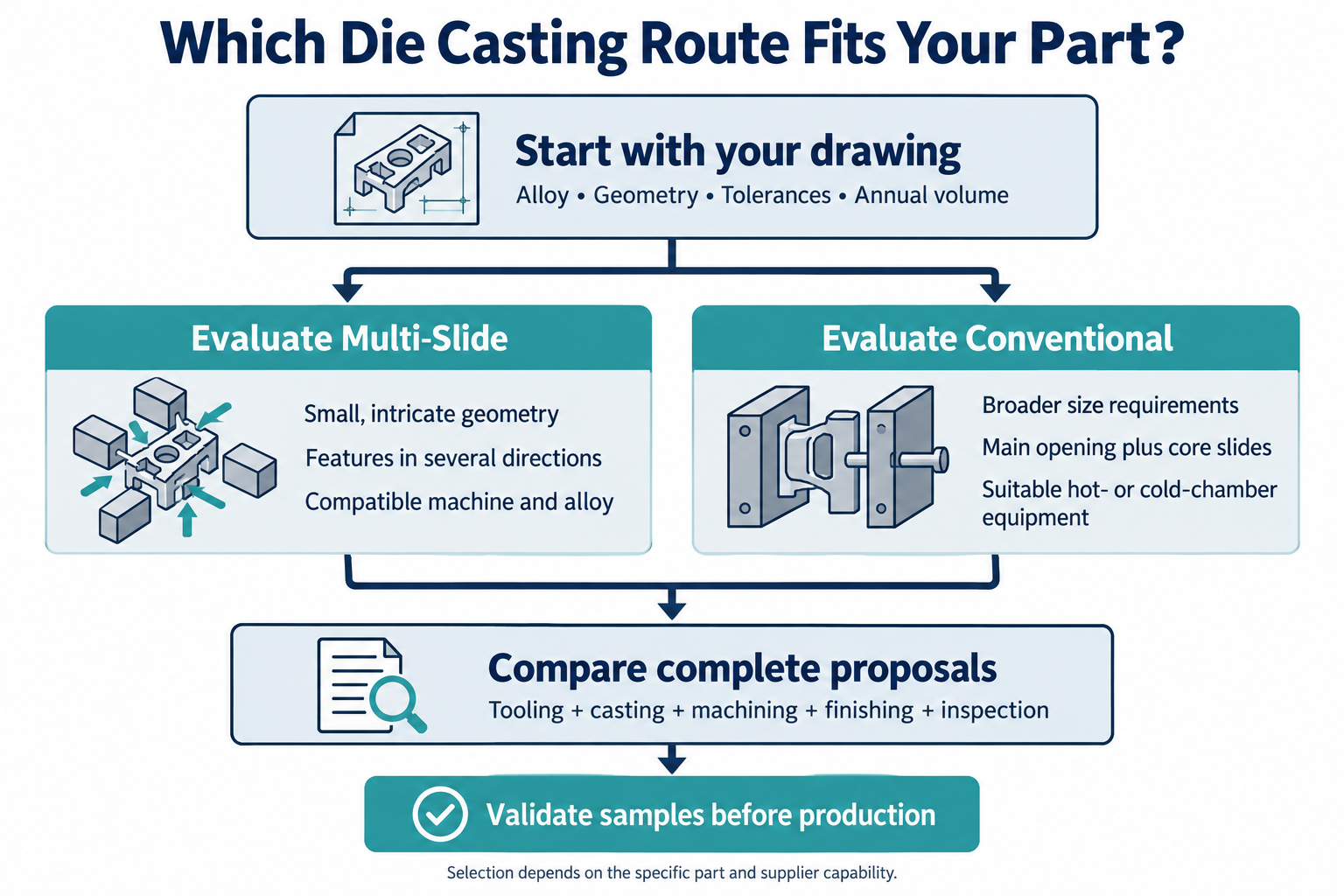
Die casting selection workflow comparing geometry, tooling, total cost, and sample validation
The examples below are selection scenarios, rather than guaranteed manufacturing routes or TOPS project records.
| Example Component | Route To Evaluate | Material Starting Point | Main Question |
| Small connector body with side openings | Multi-slide and conventional | Specified zinc alloy | Can the openings be cast without additional drilling? |
| Compact latch with several side features | Multi-slide and conventional | Specified zinc alloy | Which layout provides reliable release and simpler finishing? |
| Broad electronics housing | Conventional cold-chamber | Specified aluminum alloy | Does the machine accommodate the tool and projected area? |
| Small, simple cover | Conventional; compare alternatives if justified | Application-dependent alloy | Would additional tooling movement deliver a measurable benefit? |
| Lightweight precision component | Suitable magnesium equipment | Specified magnesium alloy | Which supplier can validate the required alloy and geometry? |
When Multi-Slide Deserves A Closer Look
Consider a multi-slide proposal when:
- Your component fits the available machine and tooling envelope.
- Several features need different withdrawal directions.
- The proposed tooling removes meaningful secondary work.
- Your recurring volume supports tooling investment.
- The supplier can demonstrate a suitable production and inspection plan.
Avoid selecting it solely because the part is small. A simple small component may have no meaningful advantage from additional tool movements.
When Conventional Die Casting Makes Sense
Consider conventional tooling when:
- Your alloy and machine requirements already favor that route.
- The component requires a larger tooling envelope.
- Most features suit the main opening direction.
- A manageable number of core slides forms the remaining features.
- The complete quotation meets your cost and quality requirements.
Do not reject conventional tooling just because your part is complex. Review the actual die concept first.
When Neither Route Is Ready
Delay production tooling if your design is still changing substantially.
For early fit checks or uncertain quantities, compare a prototype route before committing to a production die. Our CNC machining services provide another option for suitable prototype geometries.
Remember that machined prototypes do not validate production casting behavior.
What Should You Check Before Approving The Tooling?
Approve either process only after reviewing feature release, critical dimensions, and sample acceptance requirements.
Review The Design For Each Proposed Route
Use the same drawing to evaluate both tooling concepts:
| Design Feature | What To Review |
| Undercuts And Side Features | Withdrawal direction, clearance, and release sequence |
| Critical Fits | Datum strategy and whether machining is required |
| Holes And Windows | Core access, draft, filling, and inspection |
| Wall Transitions | Whether thick sections can be reduced or redistributed |
| Visible Surfaces | Acceptable tooling marks and finishing requirements |
| Machined Surfaces | Stock allowance and acceptance criteria |
Holes and windows affect both metal flow and release. NADCA recommends considering draft and filling behavior when developing these features. NADCA Holes And Windows
Avoid specifying a universal minimum wall thickness based on process name. NADCA notes that wall-thickness limits are not governed by one fixed rule. NADCA Wall Guidance
Agree On A Validation Sequence
A practical approval sequence is:
- Confirm the drawing revision, alloy, annual demand, and program life.
- Review the proposed tooling layout and secondary operations.
- Agree on critical dimensions and inspection methods.
- Produce samples using the intended production route.
- Check dimensions, finish, and required functional performance.
- Approve the process and documentation before regular deliveries.
Ask for evidence relevant to your part, rather than a general statement about “high precision.”
If pressure tightness matters, define the leak-test conditions and acceptance limit. If appearance matters, establish an agreed visual reference.
Frequently Asked Questions
Your final choice should follow the drawing, production plan, and validation results rather than the process label.
Is Multi-Slide Die Casting The Same As Four-Slide Die Casting?
Four-slide describes a particular arrangement. Multi-slide is a broader term, and equipment configurations vary.
Ask the supplier to show the proposed tooling movements.
Can Conventional Die Casting Produce Undercuts?
Yes, suitable movable cores can form certain undercuts and side features.
The geometry must allow the cores and finished casting to withdraw.
Is Multi-Slide Die Casting Always More Accurate?
No. Accuracy must be assessed for the specific dimension and tooling arrangement.
Request an agreed inspection plan for your critical features.
Is Multi-Slide Die Casting Only Suitable For Zinc?
No. Specialized equipment also exists for magnesium and other compatible alloys.
Confirm the actual machine and specified alloy before assuming feasibility.
Does Multi-Slide Eliminate CNC Machining?
Sometimes it reduces machining by casting features directly.
Your finished tolerances, threads, and functional surfaces determine which operations remain necessary.
Are Multi-Slide Molds Always More Expensive?
No. Compare complete tooling proposals for the same component.
Slide mechanisms, cavity count, validation, and maintenance requirements all influence the quotation.
Is There A Universal Maximum Part Weight?
No single weight limit defines every multi-slide machine.
Check the proposed machine’s shot capacity, tooling envelope, and clamping requirements.
What Production Quantity Justifies Either Process?
There is no universal minimum that makes either process economical.
Compare tooling investment and finished-part cost across your expected program volume.
Discuss Your Die Casting Project With TOPS Precision
TOPS Precision offers die casting, mold-making, and CNC machining services for custom components.
You can use our die casting services to begin a drawing-based discussion about material, tooling, and finishing requirements.
Choose the route that meets your finished-part requirements at a sustainable production cost. A detailed tooling proposal and validated samples provide a stronger basis than a generic comparison chart.
Contact us with your 2D drawing, 3D model, alloy, annual volume, and expected program life. Include critical tolerances, surface finish, and inspection requirements so we can review your project.


