



3-axis machining moves a cutting tool along the X, Y, and Z linear axes. It is one of the most widely used CNC milling configurations, and it suits prismatic parts, pockets, slots, holes, and accessible 3D surfaces. This guide covers how it works, its benefits, and when 4-axis or 5-axis is a better fit.
What Is 3-Axis Machining?
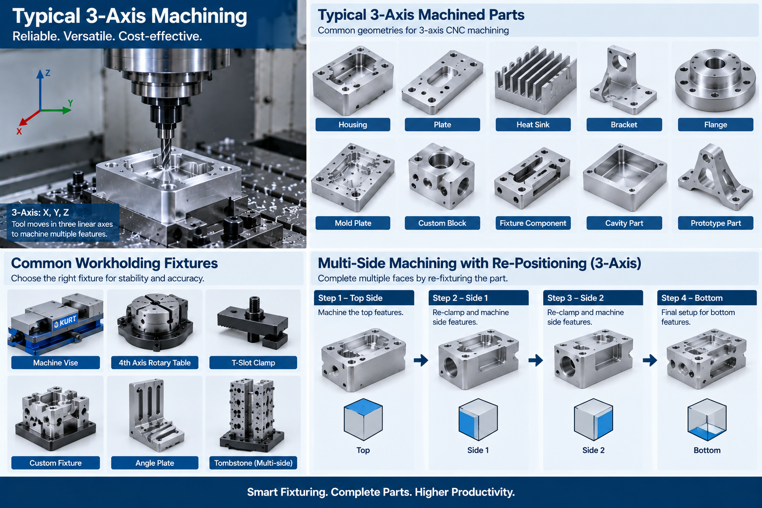
3-axis machining is CNC milling that controls three linear axes: X, Y, and Z.
The tool or the table moves along these axes while the spindle orientation stays fixed. Vertical machining centers are the most common type. Horizontal machines use the same three axes with a horizontal spindle.
Because the tool axis remains fixed, each setup can machine features accessible from that tool direction. Features on other orientations may require repositioning, additional fixtures, or multiple setups.
How Does 3-Axis Machining Work?
The controller follows a CNC program that moves the tool along a toolpath.
- The CAD model and drawing define the geometry and tolerances.
- The programmer selects suitable cutters, and CAM software generates toolpaths based on the geometry, machining strategy, and cutting parameters.
- The post-processor outputs machine-specific G-code.
- Workholding locates the part in the machine.
- The tool cuts along X, Y, and Z to the programmed path.
- Inspection verifies the critical dimensions.
Feed, speed, tool engagement, and workholding rigidity decide the result. See our guide to what is CNC milling for the wider process.
Common Machine Configurations For 3-Axis Machining
Several machine styles operate with three linear axes.
These machine categories may also be available with additional rotary axes. The table describes configurations operating in three linear machining axes.
| Machine Type | Spindle | Typical Use |
| Vertical machining center | Vertical | General milling, molds, brackets |
| Horizontal machining center | Horizontal | Production machining, box-type parts, chip evacuation |
| Bed mill | Vertical | Large and heavy parts |
| Gantry mill | Vertical | Very large plates and frames |
| Drilling and tapping center | Vertical | Holes and threads at speed |
| CNC router | Vertical | Sheet, panels, and softer materials |
Compare styles in vertical vs horizontal milling machines and 12 types of CNC machines.
Key Components
Each component affects accuracy, repeatability, and tool life.
- Spindle: holds and rotates the tool at the required speed.
- Linear axes and guideways: position the tool or table.
- Ball screws and servos: convert controller commands into motion.
- Controller: reads the program and manages motion, offsets, and tool changes.
- Feedback system or encoders: provide position feedback on closed-loop machines.
- Automatic tool changer: swaps cutters between operations.
- Coolant system: controls heat and clears chips.
- Workholding: vises, chucks, clamps, and custom fixtures.
Machine rigidity, spindle runout, and thermal stability limit the practical accuracy of any 3-axis machine.
2.5D Vs 3D Machining
2.5D machining primarily machines features at discrete Z levels, while 3D machining uses coordinated X, Y, and Z movement to follow contoured surfaces.
In 2.5D work, the cutting geometry is defined by XY motion at each depth. Typical features include pockets, slots, holes, bosses, and planar contours.
3D surface machining commonly uses ball-nose or corner-radius cutters, with cutter geometry and stepover selected according to surface shape and finish requirements. Stepover controls visible scallop height, so a finer finish costs more cycle time.
3-Axis Vs 4-Axis Vs 5-Axis
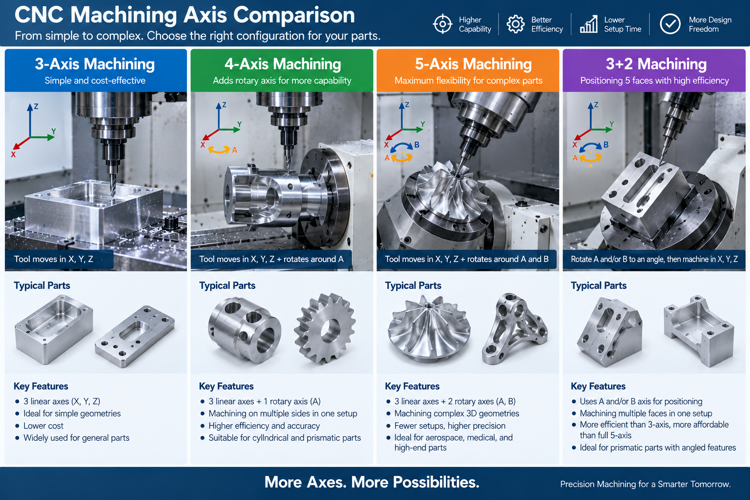
More axes add access and can reduce setups, but they also add cost and complexity.
| Factor | 3-Axis | 4-Axis | 5-Axis |
| Axes | X, Y, Z | Adds one rotary axis | Adds two rotary axes |
| Access | Features accessible from one fixed tool orientation | Features around one rotational axis | Multiple orientations and complex contours |
| Setups | More for multi-face parts | Often fewer | Often fewer |
| Programming | Simplest | Moderate | Most complex |
| Typical machine and programming cost | Lower | Moderate | Higher |
| Best for | Prismatic and 2.5D parts | Shafts and wrapped features | Complex contours and multi-face relationships |
See 4-axis CNC machining and what is 5-axis machining for the alternatives.
What Is 3+2-Axis Machining?
3+2 machining is positional five-axis machining. Two rotary axes position the workpiece or tool at a fixed angle, then the machine cuts using three linear axes.
It can reduce setups on multi-face parts without requiring continuous simultaneous 5-axis motion. The rotary axes are set once, then cutting proceeds much like a 3-axis operation. This makes 3+2 a practical middle step between 3-axis and full simultaneous 5-axis work.
Benefits Of 3-Axis Machining
3-axis machining is cost-effective, widely available, and reliable for prismatic parts.
- Often lower machine and programming cost than multi-axis machining for suitable parts.
- Simple programming and setup for 2.5D features.
- Simple machine kinematics and short, rigid tooling can support efficient material removal.
- Good dimensional control, flatness, and repeatability are achievable on suitable features with appropriate machines, tooling, workholding, and process control.
- Wide choice of cutters, including end mills and form cutters.
- Easy workholding with vises, clamps, and plates.
- Wide machine availability can make 3-axis machining practical for prototypes and production.
For geometries that do not benefit from rotary-axis access, 3-axis machining can provide the required accuracy with lower programming and machine complexity.
Limitations Of 3-Axis Machining
The fixed spindle orientation limits what one setup can reach.
- Undercuts that are inaccessible from the fixed tool direction may need special undercutting tools, extra setups, or multi-axis machining.
- Multi-face parts need extra setups, which adds cost and setup error.
- Cross-setup accuracy depends on datums, fixtures, and workholding quality.
- Deep cavities need long tools, which deflect and chatter.
- Complex curved surfaces take many passes with small stepovers.
- Angled faces may need special fixtures or a different machine.
These limits are about access and setup count, not the accuracy of the axes themselves.
When To Choose 3-Axis Machining
Choose 3-axis when the features are reachable from accessible orientations and cost matters.
- Flat plates, brackets, and housings with features on two or three faces.
- Pockets, slots, and holes with standard tolerances.
- Molds and dies where the cavity is open to one direction.
- Fixtures, jigs, and tooling plates.
- Prototypes and low-to-medium volume parts.
- Parts where a multi-axis rate is hard to justify.
Choose 4-axis when rotary indexing or machining around one rotational axis can reduce setups or improve tool access. Choose 5-axis when complex geometry or multi-face positional relationships benefit from fewer setups.
The advantage of 5-axis is not inherent accuracy. Fewer setups can reduce datum-transfer and repositioning error. See 3-axis to 12-axis capabilities compared.
Design Guidelines For 3-Axis Parts
Design for tool access and for the number of setups.
- Keep features on faces the tool can reach.
- Avoid deep, narrow pockets that need long tools.
- Use the largest practical internal radii.
- Provide tool-entry clearance, relief, or accessible approach geometry where required.
- Define a clear datum for each setup.
- Limit tight tolerances to functional features.
- Allow enough stock for the finishing pass.
Reducing setup count can lower handling and fixturing cost and reduce datum-transfer error between related features.
Tolerances And Surface Finish
There is no universal tolerance for 3-axis machining. Capability depends on feature size, material, geometry, machine condition, workholding, tooling, thermal stability, setup count, and inspection.
As a qualified general reference, many machined features fall around ±0.01 to ±0.05 mm. Tighter tolerances need feature-specific engineering review. TOPS Precision can evaluate selected critical features down to approximately ±0.005 mm where geometry, material, setup, and inspection capability permit.
Surface finish depends on cutter geometry, feed per tooth, spindle speed, tool runout, material, rigidity, and finishing strategy. On 3D contours, stepover also controls visible scallop height. Specify Ra only where surface roughness is functionally important. See CNC machining tolerances.
Materials
3-axis machining handles most machinable metals and plastics.
- Aluminum and many brass grades machine efficiently, while copper machinability varies by alloy and temper.
- Steel and stainless steel need appropriate tooling and coolant.
- Titanium needs rigid setups and controlled cutting.
- Engineering plastics such as POM, PEEK, and acrylic need care with heat and stress.
Compare options in our CNC machining materials guide.
Cost Factors
3-axis machining cost depends on setups, machine time, material, and tolerance.
- Setups: each additional setup adds labour and fixture cost.
- Machine time: material removal rate and toolpath length.
- Material: alloy type and stock size.
- Tolerance: tighter limits need more care and inspection.
- Surface finish: finer 3D finishes need smaller stepovers.
- Quantity: setup cost spreads across the batch.
- Inspection: critical features need measurement time.
Machine rate matters, but setup count, cycle time, fixturing, and inspection can have a larger effect on total part cost for some geometries. See CNC milling cost.
Applications By Industry
| Industry | Typical 3-Axis Parts |
| Industrial equipment | Brackets, plates, housings, fixtures |
| Electronics | Enclosures, heat sinks, panels |
| Medical equipment | Device housings, instrument components |
| Automotive | Brackets, prototype components, tooling |
| Aerospace manufacturing | Fixtures, tooling, brackets, housings, prototype components |
| Consumer products | Prototypes, molds, custom hardware |
Frequently Asked Questions
What is 3-axis machining?
It is CNC milling that moves the tool along the X, Y, and Z linear axes.
What is the difference between 3-axis and 5-axis machining?
3-axis uses three linear axes. 5-axis adds two rotary axes for complex orientations and often fewer setups.
Can 3-axis machining cut curved surfaces?
Yes. Coordinated X, Y, and Z motion follows contoured surfaces. It is slower than 5-axis for complex surfaces.
Can 3-axis machining cut undercuts?
Some undercuts can be machined on a 3-axis mill with specialized cutters if tool access is available. Inaccessible undercuts may require another setup, special fixturing, EDM, or multi-axis machining.
How accurate is 3-axis machining?
There is no single tolerance for all 3-axis machining. Accuracy depends on machine capability, feature size, geometry, material, tooling, workholding, thermal stability, setup count, and inspection. Tight features should be reviewed individually.
Is 3-axis cheaper than 5-axis?
For simple parts, 3-axis machining is often more economical because machine and programming complexity are lower. For multi-face parts, 5-axis machining can reduce fixtures, setups, handling, and cycle time. Compare total part cost, not machine rate alone.
When should I use 3-axis instead of 5-axis?
When features are reachable from accessible orientations and the part does not need complex orientations or multi-face relationships.
Get A Quote For Your 3-Axis Machined Part
Send your 3D model, 2D drawing, material, quantity, and tolerance requirements. Our engineers will review the geometry, count the setups, and recommend 3-axis, 4-axis, or 5-axis machining before quotation.


1 thought on “3-Axis Machining: Understanding The Technology, Applications And Benefits”