



G-code is the commonly used name for the text-based CNC programming format that tells a machine how to position and move its axes and execute machining operations. A complete CNC program also uses M-codes and address words such as X, Y, Z, F, S, and T. This guide explains how it works, its types, and where it is used.
What Is G-Code?
G-code is the common name for the text-based format that controls CNC machine motion and operations.
Strictly speaking, a part program contains several kinds of words. G words usually define preparatory and motion modes. M words handle miscellaneous machine functions. S sets spindle speed, F sets feed, and T addresses tools. Coordinate letters set positions.
Modern G-code conventions are rooted in the historical RS-274 format and the ISO 6983 family of standards. Actual implementations vary by controller and machine-tool builder.
How Does G-Code Work?
The CNC interprets program blocks in sequence, often using look-ahead and trajectory planning before commanding the machine axes.
A block is one line of program instructions. Each block contains words made of an address letter and a numeric value. The letters define what the number means.
- G words set the operation, such as G01 for a straight cut.
- X, Y, and Z set coordinates.
- F sets feed rate and S sets spindle speed.
- T selects a tool and M sets machine functions.
Some commands are modal. A modal command stays active until you change or cancel it. G01, G21, G90, and G54 are common modal examples.
Here is one example block:
G21 G90 G54 G01 X50.0 Y25.0 F250
Code meanings and allowable combinations depend on the controller. Examples in this article use common Fanuc-style conventions.
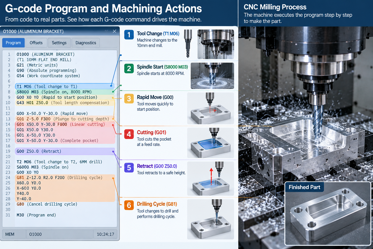
What Does A G-Code Program Look Like?
A G-code program is a sequence of blocks that runs from safe start to program end.
G21 G17 G90 G40 G49 G80
G54
T1 M06
S8000 M03
G00 X0 Y0 Z5
G01 Z-2 F150
G01 X50 F300
G00 Z5
M05
M30
Production programs commonly use a safe-start block to cancel unwanted modal states before machining begins.
What Are G-Code Words And Addresses?
A word is an address letter followed by a value. The letter gives the value its meaning.
| Address | Common Meaning |
| G | Preparatory or motion function |
| M | Miscellaneous machine function |
| X, Y, Z | Axis coordinates |
| I, J, K | Arc center offsets on many controls |
| R | Radius or cycle parameter, depending on context |
| F | Feed rate |
| S | Spindle speed |
| T | Tool selection |
| N | Sequence or block number |
| H | Tool-length offset register on many controls |
| D | Cutter compensation register on many controls |
Circular moves commonly use I, J, and K center offsets or an R radius value, depending on the controller and programming method.
What Are Modal And Non-Modal Commands?
Modal commands stay active until changed or canceled. Non-modal commands apply only to the block that contains them.
Only one command from the same modal group is normally active at a time. G00 and G01 replace each other. G90 and G91 replace each other. G17, G18, and G19 replace each other.
Understanding modal groups explains why a short program can control a long sequence of moves.
Common Types Of G-Code
A CNC part program contains G-functions, M-functions, coordinate words, feed and spindle commands, tool data, and offsets.
G-functions set motion and operating modes. M-functions trigger auxiliary machine actions such as spindle, coolant, and program flow.
| Group | Examples | Purpose |
| Motion | G00, G01, G02, G03 | Positioning and cutting moves |
| Units and mode | G20, G21, G90, G91 | Inch or millimeter, absolute or incremental |
| Planes and offsets | G17-G19, G54-G59 | Plane selection and work offsets |
| Compensation | G40, G41, G42, G43, G49 | Cutter and tool length compensation |
| Canned cycles | G81, G83, G84 | Drilling, peck drilling, tapping |
| Macros and probing | G65 and controller-specific cycles | Reusable routines, measurement, automation |
Macro syntax and probing cycles vary significantly between controllers and probe systems.
Common G-Codes And M-Codes
The following codes are common on Fanuc-style and compatible controls. Always verify your controller manual.
| Code | Function |
| G00 | Rapid positioning |
| G01 | Linear interpolation |
| G02 | Circular interpolation, clockwise |
| G03 | Circular interpolation, counterclockwise |
| G04 | Dwell |
| G17 / G18 / G19 | Plane selection |
| G20 / G21 | Inch / millimeter units on many controls |
| G28 | Reference-position return, controller-specific behavior |
| G40 / G41 / G42 | Cutter compensation off / left / right |
| G43 | Positive tool-length compensation, used with an H offset register |
| G49 | Cancel tool-length compensation |
| G54-G59 | Work coordinate offsets and systems |
| G81 / G83 / G84 | Drilling / peck drilling / tapping cycles |
| G90 / G91 | Absolute / incremental positioning |
| G94 / G95 | Feed per minute / feed per revolution |
| Code | Function |
| M00 | Program stop |
| M01 | Optional stop |
| M03 / M04 | Spindle clockwise / counterclockwise |
| M05 | Spindle stop |
| M06 | Tool change |
| M08 / M09 | Coolant on / off |
| M30 | Program end and reset |
M-code behavior is especially machine-builder dependent. Coolant, pallet changers, doors, clamps, and chip conveyors may use machine-specific M-functions. Learn more in our guide to M-code.
On many machining centers, a T word preselects or calls a tool number, while M06 commands the actual tool change.
Absolute Vs Incremental Positioning
G90 and G91 change how the control reads coordinates.
- G90 absolute positioning: coordinates are measured from the active work coordinate origin.
- G91 incremental positioning: each coordinate is measured from the current position.
Most programs use absolute positioning for clarity, then switch to incremental for repeating patterns.
Machine Coordinates, Work Offsets And Tool Offsets
Machine coordinates are tied to the machine reference system. Work coordinates locate the part within that machine space. Tool offsets then account for tool length and radius.
- G54-G59 set the work coordinate system for the part.
- G43 applies positive tool length compensation using an H register, such as G43 H01 Z50.
- G41 and G42 apply cutter compensation using a D register on many controls.
- G49 cancels tool length compensation.
This hierarchy keeps the program portable when the part moves on the table.
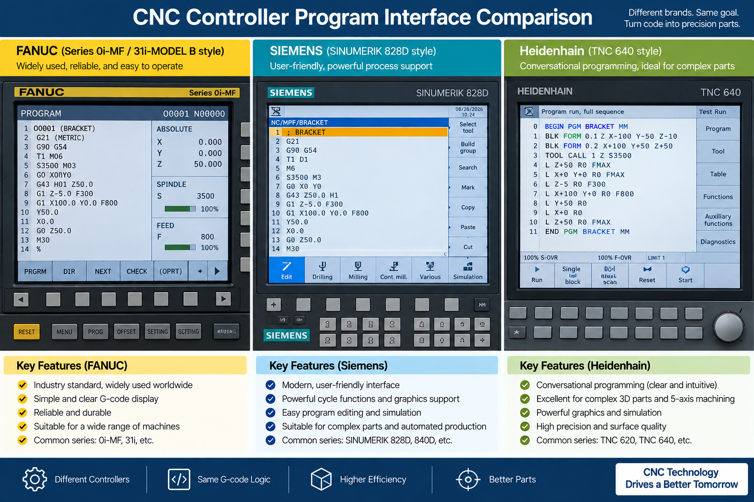
G-Code Dialects And Standards
A common core exists, but every CNC controller has its own dialect.
ISO 6983 and RS-274 define the common foundation. Fanuc-based dialects are widely used, while Siemens, Heidenhain, Mazak, and other controls use their own syntax, cycles, extensions, and controller-specific functions.
Some functions, such as probing or high-speed machining, are controller-specific. This is why a program written for one machine may not run on another. Always check the controller manual before using an unfamiliar code.
How Is G-Code Created?
Complex production programs are commonly generated with CAM software, but not all G-code comes from CAM.
- CAM toolpaths are generated from the CAD model.
- Simple parts can be programmed manually at the control.
- Conversational controls let the operator build cycles with prompts.
- Macros and parametric programs automate repeated work.
- Hand-written code still matters for setup, edits, and troubleshooting.
See our guide to CNC programming languages using G and M codes.
What Is A CAM Post-Processor?
A post-processor converts CAM toolpaths into the G-code dialect a specific machine controller expects.
It handles the differences between controllers, including cycle formats, offsets, and machine-specific functions. A correct post-processor is essential when one part is machined on different machines. See our guide to CAD files for CNC machining.
Where Is G-Code Used?
G-code drives most CNC machine tools and several other motion systems.
- CNC milling for pockets, contours, and faces.
- CNC turning for shafts, threads, and diameters.
- CNC EDM systems, using numerical-control programs for electrode or wire motion with controller-specific syntax.
- Laser, plasma, and waterjet cutting.
- Many FDM/FFF 3D printers, which use G-code or related dialects for motion, extrusion, heaters, and fans.
For machining services, see our CNC milling and CNC turning pages.
G-Code Vs CAD And CAM
In a typical modern workflow, CAD defines geometry, CAM creates toolpaths, and a post-processor outputs machine-specific CNC code.
| Stage | Main Role | Output |
| CAD | Defines part geometry | 2D or 3D model |
| CAM | Creates machining strategy and toolpaths | Toolpath data |
| Post-processor | Translates toolpaths for a machine and control | CNC program |
| CNC controller | Interprets the program and controls motion | Machine movement |
Simple parts can also be programmed manually or conversationally without a separate CAM workflow. See our guide to what is CAD.
Limitations And Risks
G-code is powerful but unforgiving. One error can crash a machine or scrap a part.
- Dialects differ between controllers.
- Wrong offsets or tool data cause position errors.
- A single typo can send a tool into the fixture.
- G-code has no built-in awareness of the physical setup.
- Traditional G-code mostly describes motion and states, not design intent. The control does not know whether a set of moves represents a pocket, boss, or sealing surface.
Complex toolpaths are normally generated and verified through CAM, simulation, and machine-specific prove-out.
G-Code Verification And Best Practices
These habits reduce risk and protect the machine.
- Simulate the program before running it.
- Use the machine builder approved simulation, graphics, dry-run, machine-lock, single-block, and override procedures as applicable.
- Verify workholding, tools, offsets, clearance planes, and travel limits before the run.
- Use a safe-start block to cancel unwanted modal states.
- Perform a first-part prove-out under controlled conditions.
- Comment blocks so the program is readable.
- Keep backups and version control of proven programs.
Frequently Asked Questions
Is G-code the same for every machine?
No. There is a common core, but each controller has its own dialect.
What is the difference between G-code and M-code?
G-functions set motion and operating modes. M-functions control machine actions such as spindle, coolant, and program flow.
Do I need to learn G-code to run a CNC machine?
CAM generates most code, but reading G-code helps with setup, offsets, and troubleshooting.
What G-codes should beginners learn first?
Common starting codes include G00 and G01 for linear motion, G02 and G03 for arcs, G17-G19 for planes, G54-G59 for work offsets, G90 and G91 for positioning, and canned cycles such as G81. Exact codes depend on the control.
Can G-code be used for 3D printing?
Yes. Many FDM/FFF printers use G-code or related dialects.
What is a post-processor?
It converts CAM toolpaths into the G-code dialect a specific machine controller expects.
Can G-code crash a CNC machine?
Yes. Incorrect coordinates, offsets, tool data, modal states, or rapid moves can cause collisions. Programs should be simulated and proved out before production.
Can you write G-code manually?
Yes. Simple parts and edits can be programmed manually. Complex 3D toolpaths are usually generated with CAM.
Get CNC Machining Guidance
Send your 3D model, 2D drawing, material, quantity, and tolerance requirements. Our engineers will review the design and recommend the right machining process before quotation.


3 thoughts on “What Is G-Code? Definition, Function, Types And Uses”