



Thread plating allowance is the dimensional space you reserve before depositing a coating on a machined thread. Define the coating and finished fit together. Then agree machining limits and final inspection. De lo contrario, a thread that passes before plating may become too tight during assembly.
Conceptual threaded parts and gauges. Color does not identify a coating; not actual TOPS production.
Why Plating Changes Thread Fit
Deposited coating occupies space on thread flanks and reduces the clearance available between mating components.
On an external thread, added material increases effective thread size. Inside a threaded hole, deposited material reduces available space. Plating both components can consume clearance from both sides of the assembly.
Pitch diameter matters because the thread flanks establish engagement. Measuring only an external major diameter cannot establish final functional fit. Your inspection plan needs to address the specified thread geometry.
Utilice nuestro machine screw thread design guide for basic terminology. This article focuses on deposited coating and acceptance after finishing, rather than general thread design.
Estimate Thread Build Up Without Treating It As A Guarantee
For an ideal 60-degree thread, uniform deposited flank thickness changes pitch diameter by approximately four times that thickness.
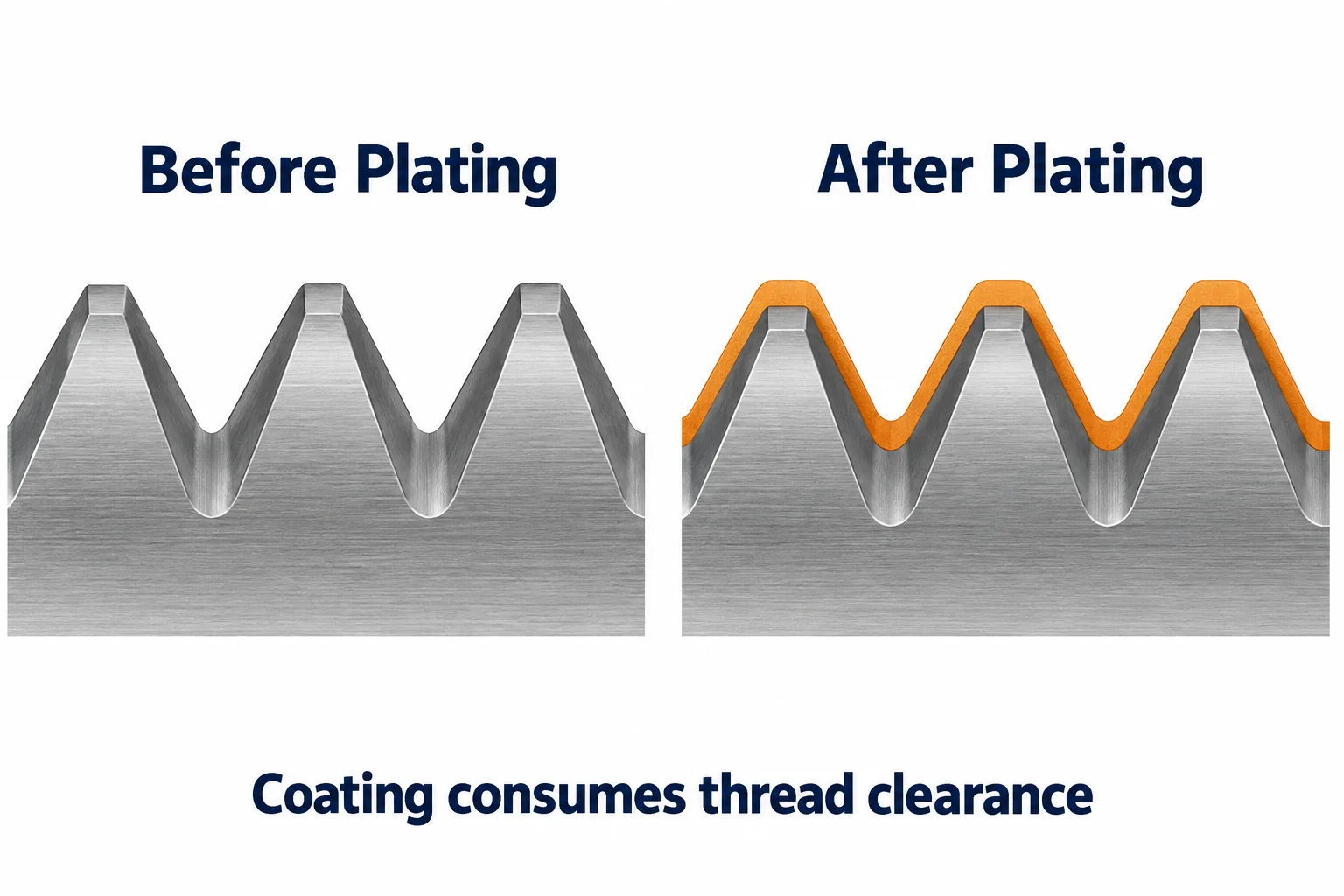
Thread Check’s technical catalog explains this 4:1 relationship for common 60-degree threads. It is a geometric planning relationship, not a complete machining or gauge specification.
Por ejemplo, assume a uniform deposited thickness of 5 micrometers on an external thread’s flanks. The estimated pitch-diameter increase is 20 micrómetros, o 0.020 milímetros.
If your illustrative process instead deposits 5–8 micrometers locally, the corresponding estimated increase spans 20–32 micrometers. These invented example thicknesses explain the calculation; they are not a recommended coating specification.
The allowable starting dimensions must still account for the actual thread limits and coating distribution. Do not simply subtract one nominal value from every thread dimension.
For internal threads, material deposition decreases the available pitch diameter. Review the mating pair rather than calculating each component independently.
Keep The Formula Within Its Scope
The relationship assumes the stated profile and uniform deposition on the relevant flanks. Real coating thickness can vary with position and geometry.
Do not apply the same estimate automatically to tapered pipe threads, other flank angles, or conversion treatments. Anodizing involves different growth behavior from deposited metal plating. Review its dimensions separately.
Define The Finished Thread Before Choosing Machining Limits
Your drawing should distinguish final acceptance requirements from the dimensions used to control machining before coating.
| Requisito | What To Specify | Por qué es importante |
|---|---|---|
| Thread identity | Estándar, nominal size, paso, handedness, and thread class | Establishes the required geometry and fit |
| Acceptance condition | Whether limits apply after the complete finish system | Prevents disagreement about when to inspect |
| Sistema de recubrimiento | Deposited metal, thickness range, post-treatments, and relevant surfaces | Defines the dimensional change to evaluate |
| Mating component | Its thread class, finalizar, and engagement length | Clearance belongs to the assembled pair |
| Inspección | Required gauges, metodos, coverage, and reporting | Makes acceptance measurable |
For ISO metric fasteners, review the applicable requirements in YO ASI 4042. Its scope concerns electroplated coating systems for fasteners; it does not automatically govern every custom threaded component.
State the contractually required edition and amendments. Avoid substituting a catalog summary for the applicable specification.
Do Not Assume A Thread Class Covers Any Coating
A tolerance designation may provide allowance, but its suitability depends on size, paso, revestimiento, and final requirements. Small or fine threads can have limited dimensional space.
Bossard’s corrosion-protection resources include coating-thickness guidance for ISO metric threads. Use the relevant technical data with your drawing and process review.
Choose Between Compensation Masking And Later Machining
Choose the production route according to where coating is required and how the finished assembly must function.
| Route | When To Evaluate It | Limitation To Resolve |
|---|---|---|
| Machine with approved coating allowance | Threads must retain the specified deposited coating | Local thickness and starting limits need control |
| Mask the thread during coating | An uncoated thread is permitted | Coverage boundaries and corrosion protection need approval |
| Machine the thread after coating | Final machining is permitted by the design | Cutting removes coating from affected surfaces |
| Revise the finish or fit | The original coating and thread limits are incompatible | Engineering approval and assembly validation are needed |
Masking should be a drawing decision, not an undocumented shop-floor workaround. Identify the masked surfaces and acceptable boundary condition.
Cutting or chasing a plated thread can expose base metal and create debris. It may change corrosion performance or violate the coating requirement. Require approval before treating it as a repair.
For general finish background, ver nuestro zinc plating guide. The required corrosion protection and thread fit must remain compatible.
Coordinate The Machine Shop And Plating Supplier
Both suppliers need the same finished-thread requirements and an agreed method for controlling coating variation.
Send the coating specification during quotation rather than adding it after machining. Identify blind threaded holes, deep engagement, small diameters, and surfaces needing special attention.
Ask where thickness will be measured and how that location represents the functional thread. A measurement on an accessible flat surface may not describe deposition deep inside a hole.
Agree how parts will be handled, limpio, protegido, and identified across outside processing. Link coating records and inspection reports to the actual batch.
For high-strength steel, also review applicable hydrogen-embrittlement controls with the finishing specialist. A satisfactory thread-fit result does not establish compliance with every material or coating requirement.
Inspect The Thread After The Complete Finish
Final inspection should verify the specified thread condition after all finish steps that affect the delivered component.
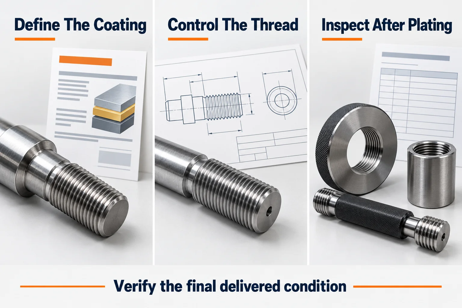
Use the appropriate calibrated thread gauges and acceptance procedure for the drawing. Distinguish pre-plating process gauges from final acceptance gauges. Their purposes and limits may differ.
Do not force a gauge into a tight thread. Investigate coating buildup, rebabas, contaminación, profile errors, or damage before changing the process.
| Controlar | Evidence It Provides | Important Limit |
|---|---|---|
| Pre-plating thread measurement | Control of the machined starting condition | Does not establish final fit |
| Coating-thickness measurement | Deposit thickness at measured locations | May not represent every thread flank |
| Final thread gauging | Conformance within the selected gauge procedure | Does not establish coating adhesion or corrosion life |
| Representative assembly test | Fit with the specified mating component | Does not replace dimensional acceptance |
Define sampling or complete inspection according to risk and the agreed quality plan. Retain identified samples when they support process approval. Revalidate relevant changes to material, coating supplier, or machining limits.
What To Do When Plated Threads Become Tight
Investigate the starting dimensions, coating condition, and acceptance method before selecting a corrective action.
Primero, confirm the drawing revision, thread identity, and gauge condition. Then compare pre-plating records with final measurements and the coating report.
Inspect the entrance, thread flanks, and engagement length for roughness, nodules, papas fritas, o daño. Check whether both mating parts received an unaccounted coating.
Contain affected parts while the cause is reviewed. Any stripping, replating, or thread rework needs approval against dimensional and material requirements. Do not assume a nut running onto one sample establishes batch acceptance.
Frequently Asked Questions About Thread Plating Allowance
Thread allowance must follow the specified profile, coating system, and finished acceptance condition.
Is Plating Thickness The Same As Pitch Diameter Growth
No. For ideal uniform deposition on common 60-degree threads, estimated pitch-diameter change is approximately four times flank thickness. Confirm applicability before setting machining limits.
Can You Plate Internal Threads
It may be feasible, but coverage and dimensional control depend on geometry and process. Ask the finishing supplier to review depth, acceso, thickness requirements, and inspection locations.
Does Passing A Gauge Before Plating Guarantee Final Fit
No. Coating changes the finished geometry. Inspect again after the required finishing sequence using the agreed final acceptance method.
Should You Always Mask Threaded Holes
No. Mask only when the design permits an uncoated thread and defines acceptable boundaries. Some applications require protective coating on those surfaces.
Can You Chase A Thread After Plating
Only with an approved process that preserves the required final condition. Chasing can remove coating and create contamination. Review corrosion and dimensional consequences first.
Request A Plated CNC Thread Review From TOPS
You can ask TOPS to review machining and finishing requirements together for your custom threaded component.
Nuestro Servicios de mecanizado CNC cover custom milled and turned parts. Confirm the coating route, supplier responsibilities, and final inspection scope for your project.
Send the drawing, material, thread specification, coating system, mating-part information, y cantidad del pedido. Identify final acceptance requirements and any masking restrictions.
Request A Threaded Part Review to discuss the machining allowance, finishing sequence, inspection plan, and quotation together.

